- radiomaster-pocket-dat - ELRS-TX-dat - ELRS-TX-setup-motor-dual-dat - motor-driver-design-dat - mosfet-dat
MIXES setup
- find refer from - radiomaster-pocket-dat
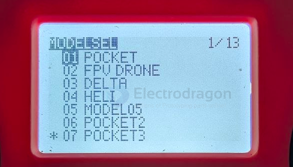
create a new model for this
Issue Analysis: Burned Board Diagnosis == mosfet driver board
- motor-driver-dead-time-protection-dat - motor-driver-dat - ELRS-TX-setup-motor-dual-dat - motor-driver-design-dat - mosfet-dat
setup guide
also Switch from "Add" to "Multiply" (The Safest Software Fix) - motor-driver-dead-time-protection-dat
Dual Motor Differential Steering (Tank Mix) Setup
This configuration maps your Throttle stick (Left Stick Vertical) to control forward/backward speed, and your Aileron stick (Right Stick Horizontal) to control left/right differential steering.
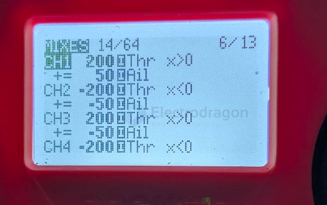
Because we are combining two distinct inputs (Speed + Steering), each channel will contain TWO lines of code on your RadioMaster Pocket's MIXES page.
🛠️ Transmitter Mixer Layout (CH1 to CH4)
1. MOTOR A (Left Motor) ── Physical Outputs 1 & 2
The left motor spins faster when you steer right, and slower when you steer left.
- CH1 (Left Motor Forward):
- Line 1: Source =
Thr, Weight =200%, Offset =-100%, Curve =Func x>0, Trim =OFF - Line 2: Source =
Ail, Weight =50%, Multiplex =Add, Trim =OFF
- Line 1: Source =
- CH2 (Left Motor Backward):
- Line 1: Source =
Thr, Weight =-200%, Offset =-100%, Curve =Func x<0, Trim =OFF - Line 2: Source =
Ail, Weight =-50%, Multiplex =Add, Trim =OFF
- Line 1: Source =
2. MOTOR B (Right Motor) ── Physical Outputs 3 & 4
The right motor spins slower when you steer right, and faster when you steer left.
- CH3 (Right Motor Forward):
- Line 1: Source =
Thr, Weight =200%, Offset =-100%, Curve =Func x>0, Trim =OFF - Line 2: Source =
Ail, Weight =-50%, Multiplex =Add, Trim =OFF
- Line 1: Source =
- CH4 (Right Motor Backward):
- Line 1: Source =
Thr, Weight =-200%, Offset =-100%, Curve =Func x<0, Trim =OFF - Line 2: Source =
Ail, Weight =50%, Multiplex =Add, Trim =OFF
- Line 1: Source =
💡 How to Add the Second Line on EdgeTX
- Go to the MIXES page on your RadioMaster Pocket.
- Highlight the target channel (e.g., CH1), press and hold the system roller, then select
Insert After. - A secondary line will appear nested directly underneath that channel.
- Edit this new line to set your steering parameters (
Source = Ail, etc.). Ensure the Multiplex option at the bottom remains set toAdd.
🔍 Multimeter Verification Protocol (Before Connecting Driver Board)
Disconnect your IN1/IN2 motor driver board and measure the bare receiver signal pins against GND:
-
Sticks Completely Centered: Outputs 1, 2, 3, and 4 must all read
0V(Dead Stop). -
Push Throttle Straight UP: Output 1 (Left Fwd) and Output 3 (Right Fwd) must smoothly climb to
3.3V. Outputs 2 and 4 must stay at0V. -
Throttle Straight UP + Move Steering RIGHT: Output 1 stays high near
3.3V, while Output 3 drops significantly toward1.6Vor lower. This drops power to the right motor, causing the vehicle to pivot right.
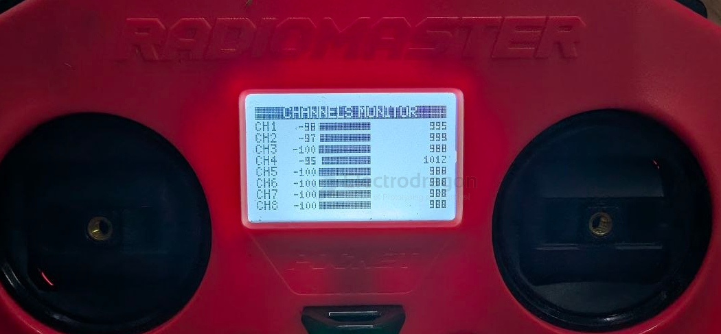
final result and initiate screen
ELRS-RX setup
