this is a succsessor of NWI1252-dat, further add RS232-dat interface
Info
product url - NWI1252-dat
Board Map, Dimension, Pins, chip info, Use Guide, Setup Jumper, etc.
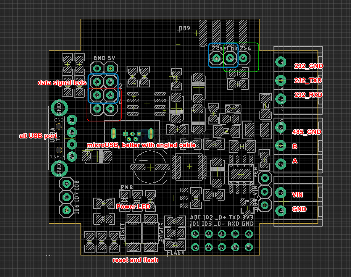
red box
- data communication LED indicator
- spare pins
- IO6 IO7 IO8
- ADC IO2 D+ TXD 3V3
- IO1 IO3 D- RXD GND
- EN button and flash button = IO10
- power LED
- flash button programmable LED = IO9
yello box
- Power input
Green Box
- USB A native USB
- micro USB native USB, same
Blue Box DB9 - V2
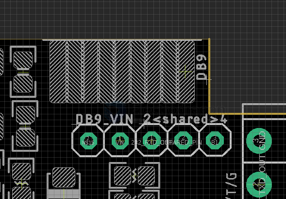
- set DB9_VIN jumper to give supply to pin 6 (from bottom left 1)
- set shared to left 2 for RS232, for share pin 2 (from top right 2)
- set shared to left 2 for RS485, for share pin 2 (from top right 2)
Blue box
- jumper, RS232 / RS485 output selector
- GND / +5V
- DB9 connector, includes a jumper selector for pin2
cable terminal output RS232 / RS485,
dcdc-down-dat == 3A, Wide Input Range, Step-Down Converter
Wide input voltage range:
– TPS5430: 5.5V to 36V
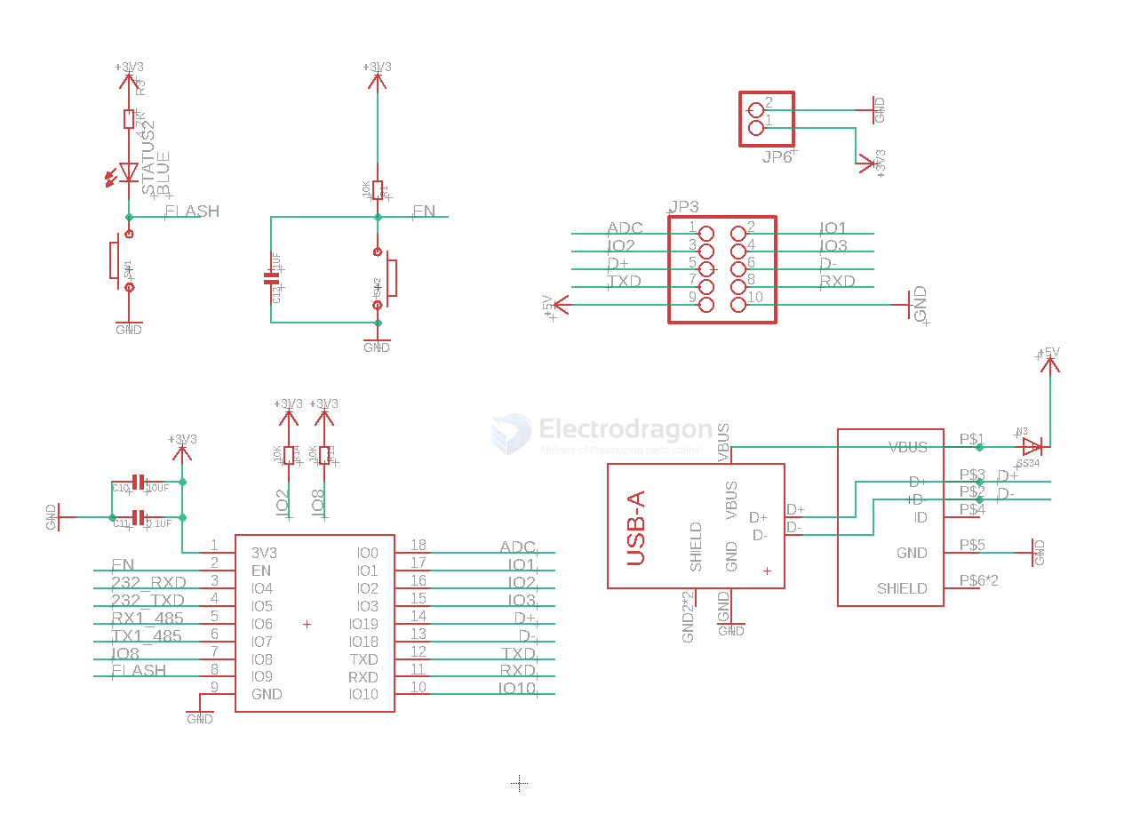
main controller part SCH
Applications, category, tags, etc.
Demo Code and Video
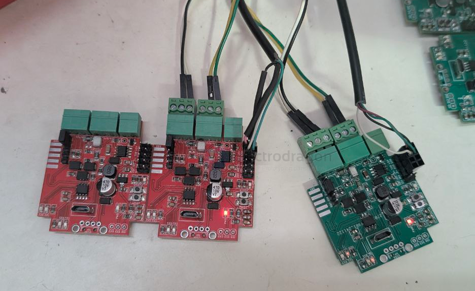
note the RS232-dat interface should be twisted, wire as TX-RX and RX-TX
default flash data
"C:\Users\Administrator\AppData\Local\Arduino15\packages\esp32\tools\esptool_py\5.1.0/esptool.exe" --chip esp32c3 --port "COM15" --baud 921600 --before default-reset --after hard-reset write-flash -z --flash-mode keep --flash-freq keep --flash-size keep 0x0 "C:\Users\Administrator\AppData\Local\arduino\sketches\45267CD3CF422CD163E590AF8B86E223/NWI1254-3.ino.bootloader.bin" 0x8000 "C:\Users\Administrator\AppData\Local\arduino\sketches\45267CD3CF422CD163E590AF8B86E223/NWI1254-3.ino.partitions.bin" 0xe000 "C:\Users\Administrator\AppData\Local\Arduino15\packages\esp32\hardware\esp32\3.3.1/tools/partitions/boot_app0.bin" 0x10000 "C:\Users\Administrator\AppData\Local\arduino\sketches\45267CD3CF422CD163E590AF8B86E223/NWI1254-3.ino.bin"
update logs and issues
apps
- PLC-dat - modbus-dat - RTU-dat
ref
legacy wiki page