usage
Power supply
Wide input voltage range: 5.5V to 36V - dcdc-dat
USB
- Soldering wirings GND / D+ (green) / D- (white) / VUSB = USB-cable-dat

Board maps
V1

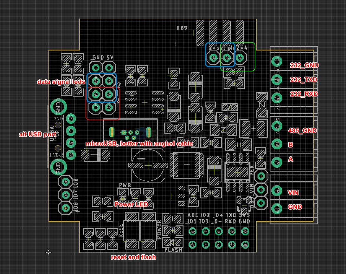
- set red and yellow jumpers for RS485
-
set blue jumpers for RS232
- DB9-dat
V0 (obseleted)

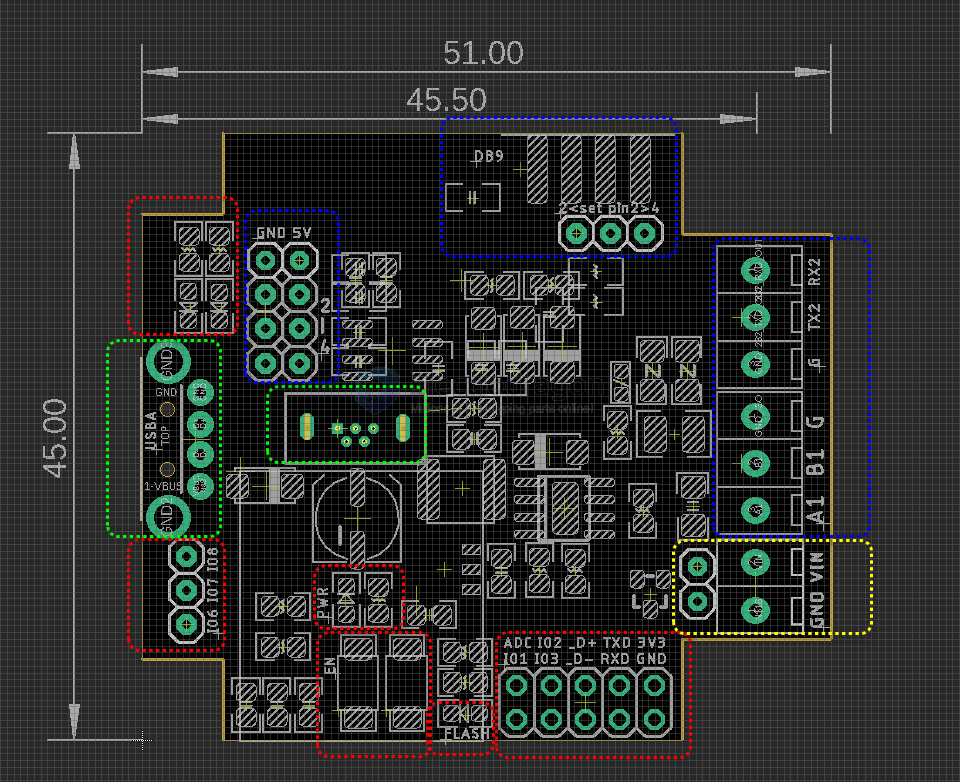
red box
- data communication LED indicator
- spare pins
- IO6 IO7 IO8
- ADC IO2 D+ TXD 3V3
- IO1 IO3 D- RXD GND
- EN button and flash button = IO10
- power LED
- flash button programmable LED = IO9
yello box
- Power input
Green Box
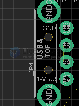
- USB A native USB
- micro USB native USB, same
Blue box
- jumper, RS232 / RS485 output selector
- GND / +5V
- DB9 connector, includes a jumper selector for pin2
- cable terminal output RS232 / RS485,
demo vidoe
- https://www.youtube.com/shorts/bP3zJOAH-PU
- https://www.youtube.com/shorts/yHJsV8njQ3E
- https://www.youtube.com/shorts/BCYFG2o0iMA
- https://www.youtube.com/shorts/9svPSDBRmKE
and reference demo test code - https://github.com/Edragon/Arduino-ESP32/tree/master/NWI/NWI1252
Note
- Case is super rigid, very difficult to open it, use a sharp tool to pry it
Design logs
| updates | status | version |
|---|---|---|
| changed and moved a few pins | added | V2 |
| simutaniously RS-232 / RS-485 data | added | V2 |
| flipped side DB-9 | added | V2 |
| power reverse protection | added | V1 |
| DC barrel 2.1mm barrel plug | not added | V1 |