Setup Scenarios
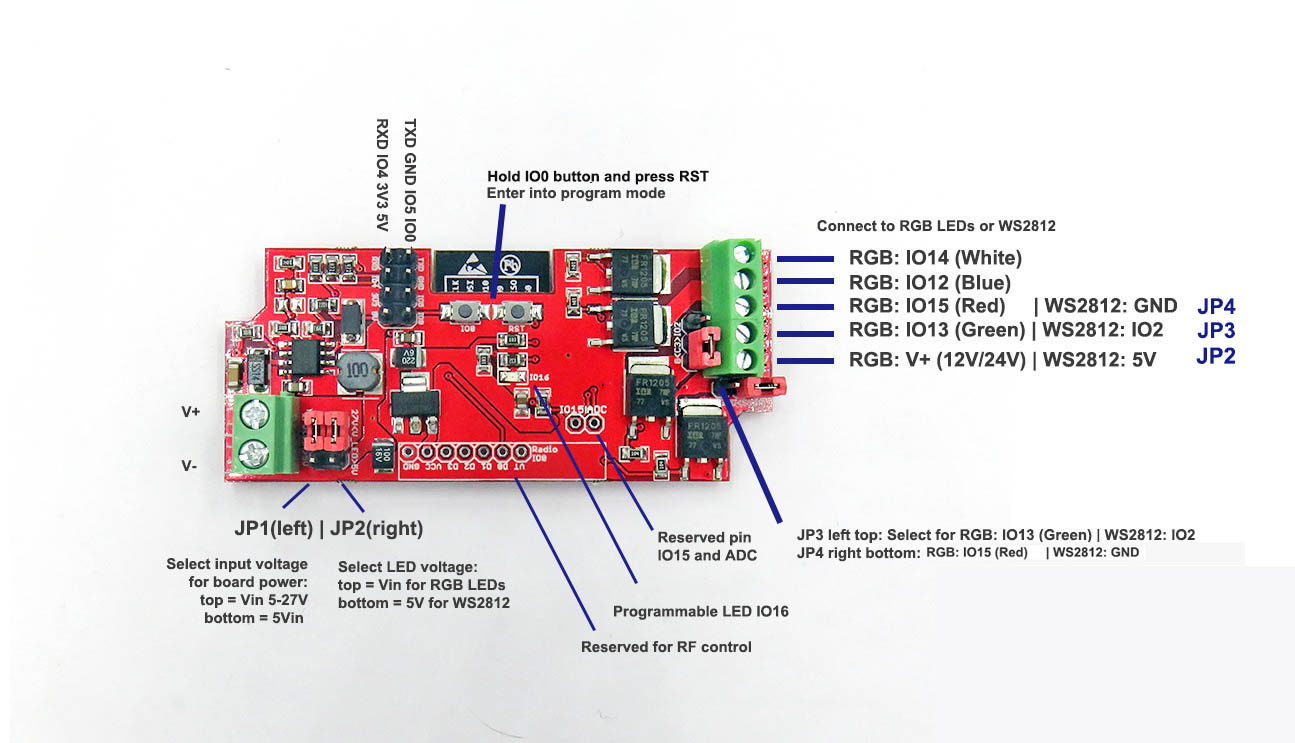
| Target | Power Supply Input | JP6 (strip power) | JP7 (board power) | JP8 | JP9 |
|---|---|---|---|---|---|
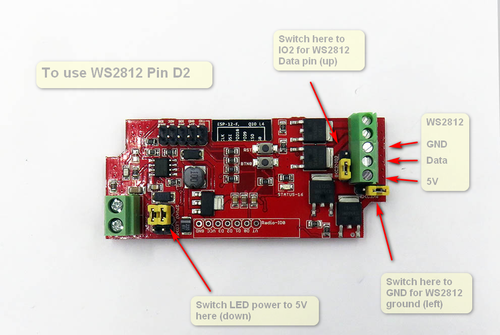
| 5V WS2812 LED Strips | 5-27V | 5V | VIN | IO2 | GND |
| 5V WS2812 LED Strips | 5V | 5V | 5V | IO2 | GND |
| 5V WRGB 4ch LED Strips | 5-27V | 5V | VIN | GR | RE |
| 5V WRGB 4ch LED Strips | 5V | 5V | 5V | GR | RE |
| 12 / 24V WS2812 LED Strips | 12V or 24V corresponding | VIN | VIN | GR | RE |
| 12 / 24V WRGB 4ch LED Strips | 12V or 24V corresponding | VIN | VIN | GR | RE |
- Note1: 12 / 24V WRGB 4ch LED Strips is the default option which set on the board
Setup Explantion V2
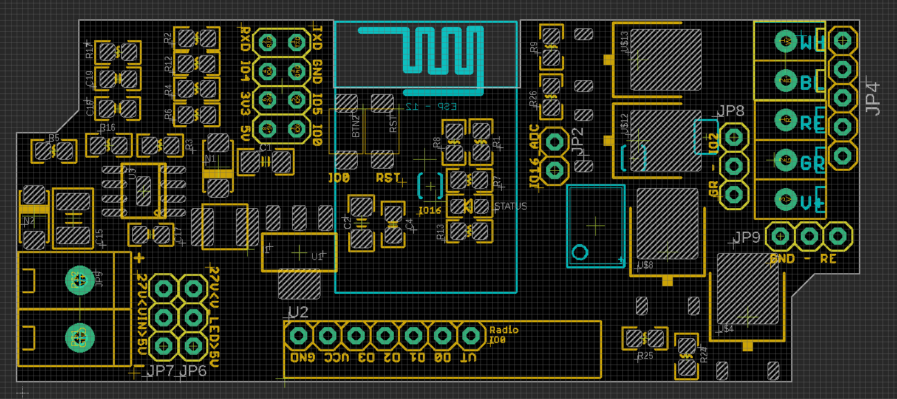
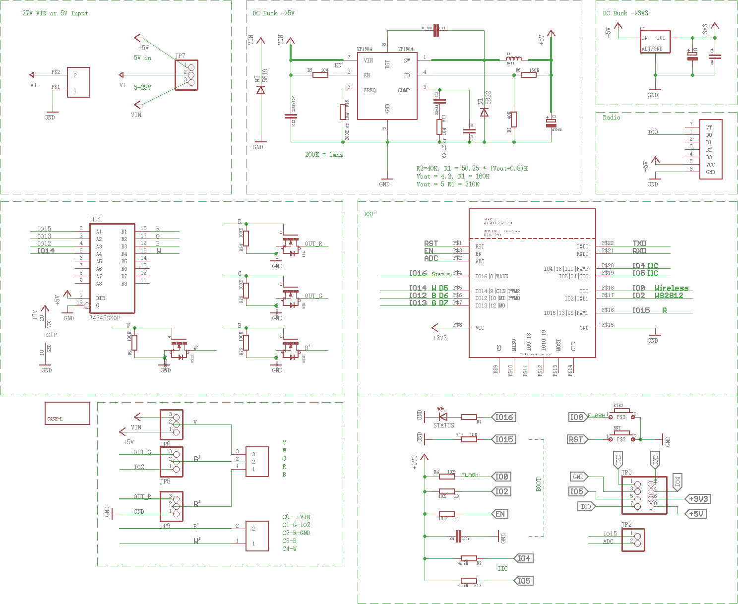
Schematic
Frontside Other Jumpers
- output JP4 only use pin 3-5 from top to bottom: GND, DAT_5V, 5V
Backside Jumper
- SJ1+SJ2 set IO2 via logic shifter to 5V output for WS2812 signal
- SJ3 = IO16 LED connection control
Accessories
- Reserved pins for our RF-LINK EDRF2 module here. (one channel trigger IO0 Low)
- https://www.electrodragon.com/product/rf-switch-receiver-433315mhz-wdecoder/
Demos
- https://www.youtube.com/watch?v=_kBS72xQPqQ
ref
- nwi1124
-
old wiki link: https://www.electrodragon.com/w/ESP_Light
- NWI1124-DAT - NWI1125-DAT - NWI1126-DAT