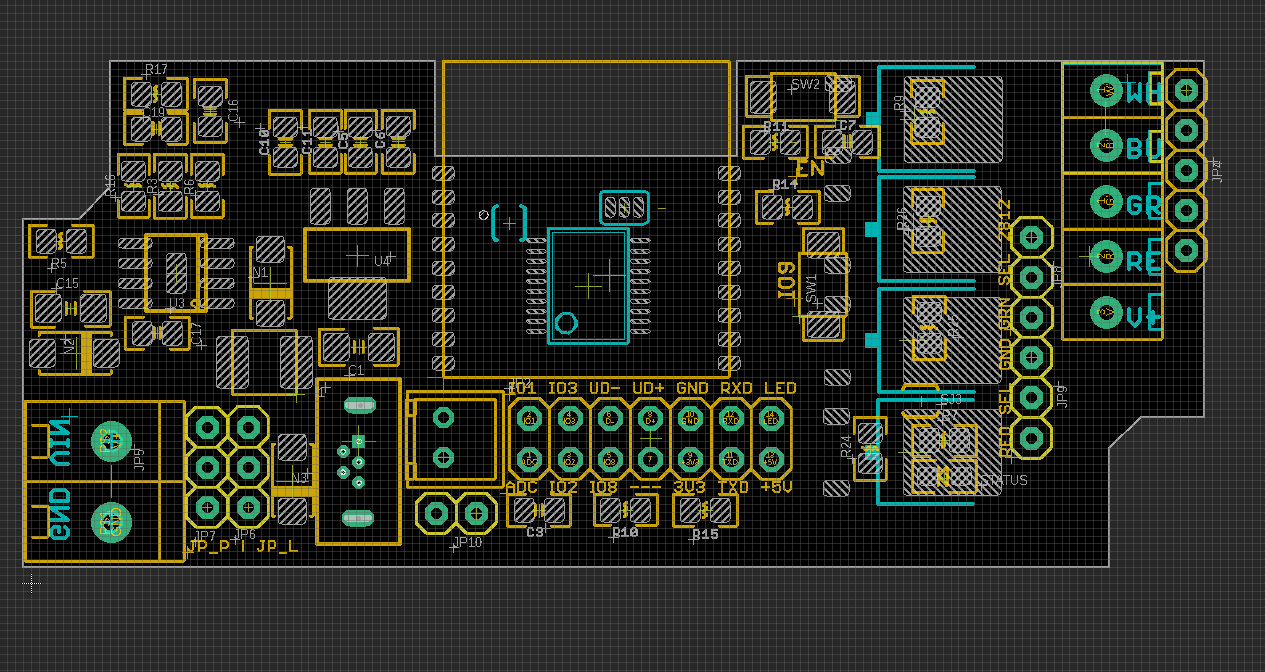
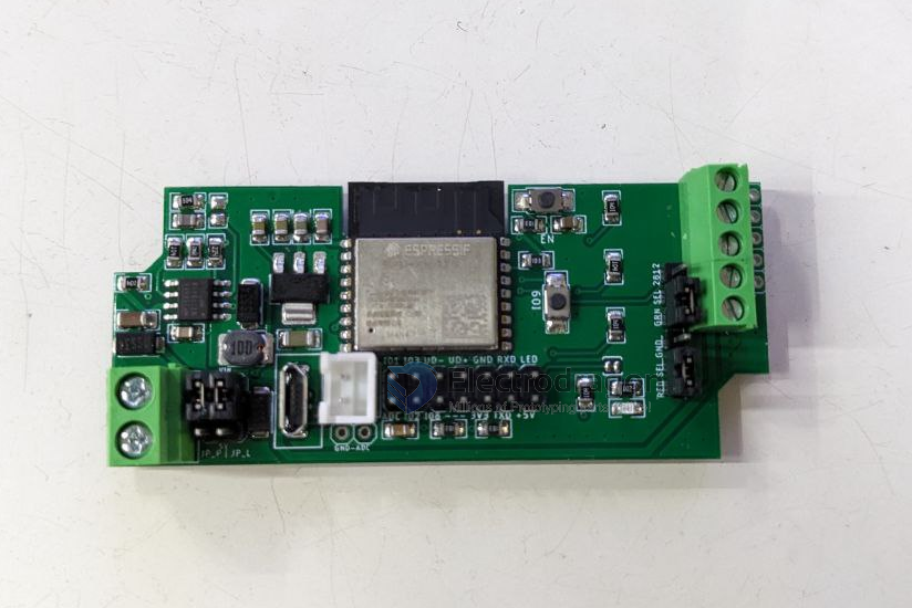
Pin Definitions
#define OM_LED 10 // on module led
#define WS_LED 9 // WS2812, select by jumper

#define addc 0

#define W_LED 4 // white
#define B_LED 5 // blue
#define G_LED 6 // green
#define R_LED 7 //red
- IO9 button = program mode pin
- EN button = reset pin
- programmable LED pin 10
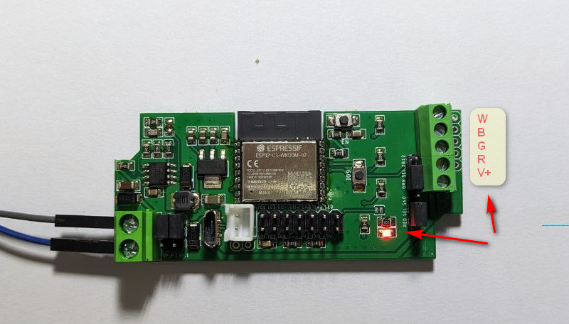
Wiring Diagram
Wiring for RGBW LED Strips
Wiring for WS2812_5V
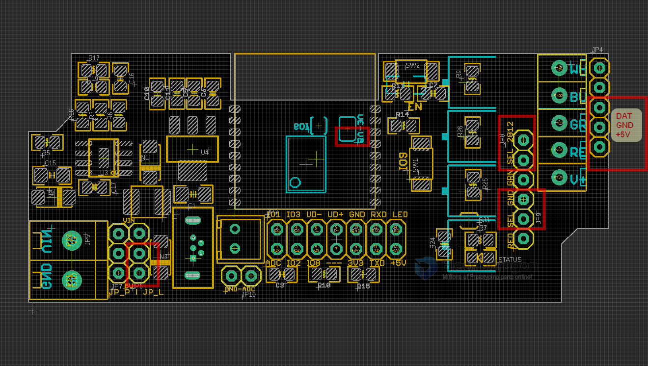
Jumpers
| Jumper Name | Option 1 | Option 2 | Function | Note |
|---|---|---|---|---|
| JP_P | 5V | 6~28V | board system power supply | |
| JP_L | 5V | 6~28V | led strip power supply | |
| JP 8 (top) | ws2812_dat | Green | reused pins for WRGB channels or WS2812 | |
| JP 9 (bottom) | ws2812_gnd | Red | reused pins for WRGB channels or WS2812 | |
| back_jumper | ws2812_dat_3.3V | ws2812_dat_5V | set ws2812 dat pin to 5V output default | default |
- if you are still confuse, please check the use case at the end of this page.
Programming
- Programming guide please refer to page USB-TTL-dat
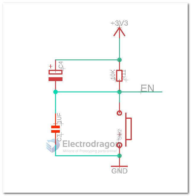
Core Module Sch
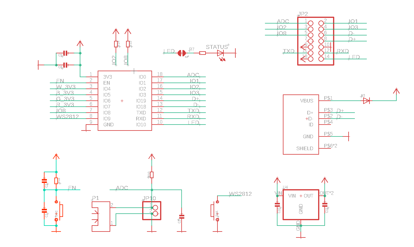
Peripheral schamtic please refer to NWI1124-DAT
quick test
- find demo code at https://github.com/Edragon/Arduino-ESP32
- find your board IP address, verify it in browser: http://192.168.8.165
- try the test commands to turn off on board prog LED: http://192.168.8.165/io/10/val/0
- in which, IO is 10 and IO voltage level is 0
Note
- ESP32-USB-dat failed on code testing, may work or not, consider it is not working if you buy.
- price discount: 10% for 49-149pcs, 15% for 150pcs+
Update Log
- New USB footprint to simplified the production process and reduce failure rate
- Tested USB Functions working fine by customers feedback
Version Logs
2023-1101
custom only
- C4 = 100uf/10V
ref
-
read more information regarding how to use the chip here ESP32-C3-dat - ESP32-C3-WROOM-02-DAT
- NWI1124-DAT
- NWI1125-DAT
- ESP32-DAT - code at arduino-esp32-dat
jumper setup cases
Case 1: Control RGBW 4 channel LED Strips
- LED strips power supply 6~28V (12V or 24V)
- Board power supply 6~28V
| jumper name | set |
|---|---|
| JP_P | 6~28V (top) |
| JP_L | 6~28V (top) |
| back_jumper | default |
| JP_8 | GNR (bottom) |
| JP_9 | RED (bottom) |
Case 2: Control WS2812 LED Strips
- LED strips power supply 5V
- Board power supply 6~28V
| jumper name | set |
|---|---|
| JP_P | 6~28V (top) |
| JP_L | 5V (bottom) |
| back_jumper | default |
| JP_8 | WS2812_data (top) |
| JP_9 | WS2812_gnd (top) |
demo video
- video 3 - use I2C - https://youtube.com/shorts/UG-1v1mZk8A?si=PcT6opcI4V1srDCq
- video 2
- running LED Strips at 1A / 24V for 1 hour, the board's temperature raise a little.
- https://www.youtube.com/shorts/aCjfessCOVM
- video 1
- https://twitter.com/electro_phoenix/status/1610204098019880961
Default test firmware
Default firmware, right bottom LED blink, drive common 4ch RGBW LED strip to blink