coupling combination
🛠️ 稳固机器人传动选型与三重锁紧方案说明
针对你的双出轴减速电机(M6外螺纹 + D型铣平面 + 轴心M3内螺纹)连接 6mm负载端传动轴 的高性能机器人结构,以下是整合了锁紧形式对比、选型建议及终极安装流程的技术文档,方便直接复制保存。
一、 核心锁紧形式深度对比
在机器人高频正反转和急停的动态运动中,不同固定形式的受力模型和表现有着本质区别:
| 固定形式 | 受力模型 | 零背隙(传动精度) | 核心优缺点分析 | 针对你项目的建议 |
|---|---|---|---|---|
|
纯顶丝式 (Set Screw) |
点接触 依靠螺钉尖端死顶轴面 |
❌ 有微小旷量 交变受力下易松动 |
优点:成本极低。 缺点:极易产生微动磨损,正反转易打滑并咬伤轴面。 |
不推荐单独使用,仅可作为D面的辅助死锁。 |
|
纯夹紧式 (Clamping) |
面接触 360°圆周全包围抱紧 |
纯零背隙 受力均匀抗扭高 |
优点:锁紧力矩大,不伤轴,无机械晃动间隙。 缺点:极端死卡冲击下有微量滑移风险。 |
强烈推荐作为基础结构,提供高刚性。 |
|
夹紧+顶丝并用型 (Combination) |
点面结合 全包围摩擦 + 物理销钉 |
纯零背隙 消除任何机械公差 |
优点:完美结合两者的优点,兼顾刚性、无间隙与绝对抗滑。 缺点:需要特定标准件。 |
🌟 终极首选 完美利用你电机轴的D型平面。 |
二、 为什么已经有“夹紧式”还需要“顶丝”?
如果轴是纯圆柱光轴,纯夹紧式确实不需要顶丝(顶丝在光轴上极易松动且起反作用)。但因为你的电机轴自带D型铣平面,选择“夹紧+顶丝并用型”可以达成“1+1>2”的效果:
- 顶丝作为“安全销”:顶丝垂直拧紧在D面上,形成了物理刚性阻挡(机械死锁)。只要螺丝不断,轴在圆周方向绝对不可能发生大幅度打滑。
- 夹紧作为“消隙器”:侧面切缝的夹紧螺丝收紧后,360°抱死轴身,彻底消除了顶丝与D面由于加工公差带来的微小晃动旷量(Backlash),同时承担了大部分扭矩,防止顶丝咬坏D面。
三、 终极修复:三位一体锁死法(安装顺序指南)
为了保证机器人两端负载受力不均时绝对同步、永不打滑、轴向不窜动,请采购 “带内部台阶孔(Center Stop / Counterbore)的变径(6mm转Xmm)夹紧并用型刚性联轴器”,并严格按照以下步骤组装:
1. 第一道防线:顶丝死锁圆周(D面定位)
- 动作:将联轴器套上电机的M6轴。
- 要点:必须确保联轴器上的顶丝孔百分之百正对轴的D型平面中心,将其用力拧紧。
- 效果:确立几何对称初始位置,提供第一重圆周刚性阻挡。
2. 第二道防线:M3轴心螺栓拉紧(轴向压紧)
- 动作:使用一把加长杆内六角扳手,从联轴器前端(负载端空孔)一路伸到最深处。
- 要点:插入 M3内六角杯头螺栓(下方加弹簧垫圈),穿过联轴器内部的中心台阶缩口,拧入电机轴心的M3内螺纹孔中。
- 效果:产生巨大的轴向拉力,将联轴器死死向后拉,牢牢压紧在电机的轴肩上,彻底杜绝轴向前后窜动。
3. 第三道防线:侧面螺丝抱死(消除背隙)
- 动作:使用扳手用力拧紧联轴器侧面的切缝夹紧螺丝。
- 效果:360°全包围抱紧M6外圆周,消除所有微小机械间隙,平摊扭矩应力。
4. 负载轴连接
- 动作:将你的 6mm负载端传动轴 插入联轴器剩下的另一端空孔内。
- 要点:拧紧负载端侧面的夹紧螺丝(如果负载轴也能磨出一个D面并配合顶丝锁紧,效果达到工业级极限稳固)。
💡 固化提示:在进行上述所有螺丝(M3轴心螺丝、顶丝、夹紧螺丝)的最后总拧紧时,务必在螺纹处涂抹一滴中强度液体螺纹锁固胶(如乐泰 Loctite 242 蓝胶),静置24小时完全固化后方可开机运动,以防高频振动导致螺丝微量松动。
type of coupling
keyed coupling == 键槽联轴器
单劈裂刚性联轴器
带顶丝 夹紧 双重锁紧 联轴器
一、 受力模型对比(为什么夹紧式更稳固)
- 夹紧式(Clamping Style)—— 面接触
原理:利用侧面切缝和螺栓收紧,使联轴器的内孔整体缩小。
受力状态:对轴形成 $360^\circ$ 的全圆周面接触。它依靠极大的均匀摩擦力来传递扭矩。
优势:
- 零背隙(Zero Backlash):因为是全包围抱死,轴和联轴器之间没有任何微小间隙,极其适合频繁正反转、急停高动态运动的机器人关节。
不伤轴:力量均匀分散,不会在硬化光轴上留下凹坑或划痕。
- 多顶丝式(Set Screw Style)—— 点接触
原理:联轴器本身是一个死孔,靠 2 个或多个螺钉硬生生“顶”在轴的表面。
受力状态:属于极极端的点接触。
劣势:
- 正反转极易松动:机器人高频正反转时,顶丝尖端在轴面会受到交变切向力的剧烈揉搓,时间一长螺丝必然松动、打滑。
- 伤轴且产生旷量:顶丝会在轴上咬出小坑。如果多次拆装,轴表面变形后,同心度会变差,且频繁反转时会在小坑里产生微小的微动磨损(产生机械晃动间隙)。
rigid clamping coupling with Counterbore
在工业级和高精度的微型机器人设计中,用 M3 螺栓(作为轴心拉杆螺丝)配合 Rigid Clamping Coupling(刚性夹紧式联轴器) 是一种非常经典且极度稳固的组合。
不过,标准的刚性夹紧联轴器本身只是一个通孔套筒,要让它完美支持你的 M3 轴心螺栓,联轴器需要满足一个关键的结构特征:内部必须带有一个中心台阶孔(Counterbore / Center Stop)。
具体是如何实现的,以及安装时需要注意什么,为你详细拆解:
- 它是如何支持 M3 螺栓锁死的? 当标准的刚性夹紧联轴器(Rigid Clamping Coupling)套在你的 M6 电机轴上时:
轴心锁死(轴向防脱):M3 螺栓从联轴器的负载端(另一头)伸进去。联轴器内部中间有一个变小的台阶,M3 螺栓的螺帽(通常是杯头内六角螺丝)会卡在联轴器内部的台阶面上,而螺纹部分穿过去,直接拧进你电机轴心的 M3 孔里。
当你拧紧这颗 M3 螺栓时,它会产生巨大的轴向拉力,像拉杆一样把联轴器死死往后拉,牢牢压紧在电机的轴肩上。
侧面夹紧(圆周防打滑):与此同时,联轴器本身的侧面夹紧螺丝(Clamping Screws)拧紧,360度抱死电机的 M6 外圆周和 D 型面。
这两种力组合起来,就形成了我们前面提到的高强度锁死。
L type coupler
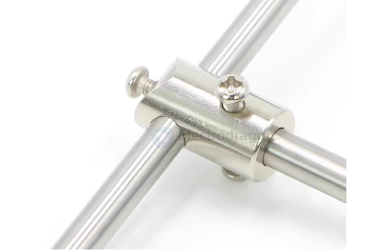
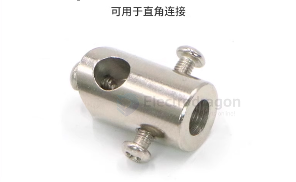
Shaft Coupler
A shaft coupler is a mechanical component used to connect two rotating shafts. It primarily functions to transmit torque while allowing for slight axial, radial, or angular misalignments.
Types of Shaft Couplers
1. Rigid Coupler
-
Features: No elasticity, provides a solid connection, requires precise shaft alignment.
-
Applications: High-precision CNC machines, industrial machinery.
2. Flexible Coupler
-
Features: Can absorb slight misalignment, reduce vibration, and minimize impact.
-
Common Types:
-
Jaw Coupling – Uses an elastomer insert to absorb vibrations; suitable for stepper and servo motors.
-
Bellows Coupling – High torque transmission capability, ideal for precision applications.
-
Disc Coupling – Used in high-speed and high-precision applications, such as robotics and aerospace.
-
Jaw Coupling – Uses an elastomer insert to absorb vibrations; suitable for stepper and servo motors.
3. Universal Joint (U-Joint)
-
Features: Allows for larger angular misalignment, commonly used for shafts that are not in perfect alignment.
-
Applications: Automotive drivetrains, heavy machinery.
4. Oldham Coupling
-
Features: Compensates for significant radial misalignment, commonly used in automation and 3D printing.
Key Functions of Shaft Couplers
✅ Torque Transmission – Connects the motor to the driven shaft for power transfer.
✅ Misalignment Compensation – Allows slight shaft misalignment, reducing stress.
✅ Vibration & Shock Absorption – Helps dampen vibrations and protect mechanical components.
✅ Equipment Protection – Some couplers act as safety devices in case of overload.
Why Diaphragm Couplers (Disk Couplers) Are Superior
Yes, a Diaphragm Coupler (also known as a Disk Coupler) offers significantly better gripping power than a standard set-screw coupler. For a high-torque project like your Rover V2, this is a professional-grade upgrade.
1. Clamping vs. Poking (The Grip Factor)
The primary reason it works better is the fixing method:
- Your Current Coupler: Uses a "Set Screw" that pokes a single point. On an aluminum tube, this just dents the metal and slips.
- Diaphragm Coupler: Most use a Clamping Design. When you tighten the side bolt, the entire inner circumference of the coupler shrinks to "hug" the shaft 360°.
- Result: The friction is distributed over the entire surface area of the shaft, making slippage nearly impossible.
2. Eliminating Backlash (Precision)
In robotics, you often have frequent "Start-Stop-Reverse" movements.
- The Problem: Set screws eventually wiggle and create "play" (backlash). Every time the motor reverses, the screw slams against the side of its hole, widening it.
- The Solution: Diaphragm couplers are Zero-Backlash. The torque is transmitted through thin stainless steel springs (the disks). There are no moving parts to "clatter," which keeps the connection tight forever.
3. Comparison Table: Why Upgrade?
| Feature | Entry-Level (Set Screw) | Diaphragm (Clamping) |
|---|---|---|
| Grip Strength | Low (Point contact) | High (Surface contact) |
| Shaft Damage | Heavy (Scratches/Dents) | Zero (Safe for Alu tubes) |
| Misalignment | Rigid (Causes vibration) | Flexible (Absorbs offset) |
| Longevity | Low (Screws loosen) | High (All-metal durability) |