- standard coordinate file == fab-dat/fab-PCBA-dat/export-coordinate-dat/standard-1.csv
Preparation == CSV coordinate file
- The software's default unit is millimeters (mm), so your EDA drawing board software should also be set to millimeters, not mils.
- For component drawing packages, try to place the center point at the geometric center rather than at PIN1.
-
The exported CSV file must contain:
- Designator,
- Footprint,
- Mid X,
- Mid Y,
- Ref X,
- Ref Y,
- Layer,
- Rotation,
- Comment or "Designator,
- Footprint,
- X,
- Y,
- Layer,
- Rotation,
- Comment
CSV file header like
shoud be like this:
Designator,Footprint,Mid X,Mid Y,Ref X,Ref Y,Pad X,Pad Y,Layer,Rotation,Comment
and data line like
C1,R0201,14.4mm,46.2mm,14.4mm,46.2mm,14.06mm,46.4mm,T,330,Comment
PCB Coordinate File Terms
-
Mid x y
This refers to the "midpoint" coordinates of a component or feature on the PCB. It typically marks the central location of the component, where the component is positioned relative to others in the layout.
x and y values specify the exact location on the board.
-
Ref x y
This stands for the "reference" coordinates of a component, marking its reference point (often pin 1 of a component, for example) on the PCB.
It's used to define the component's placement or to reference the component for design or testing purposes.
-
Pad x y
A "pad" refers to the physical area on the PCB where components (like resistors, capacitors, or ICs) are soldered.
- Pad x y coordinates specify the location of a pad on the board, often corresponding to the component's footprint.
- These coordinates are essential for defining the connections between components via soldering pads.
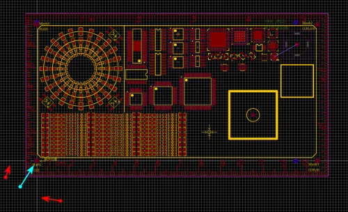
PCB Drawing Board Origin Mark Point
You must set a PCB origin position and understand where that origin is located on the PCB. We will use this in the next step when setting the PCB origin position.
Generally, it is the intersection of two white lines.
export methods for eagleCAD
To export component coordinates from Eagle CAD for pick-and-place assembly, go to File > Export > Mount SMD, which will generate two files:
one for the top side (.mnt) and one for the bottom side (.mnb).
export methods for kicad (??)
export methods for allegro (NA)
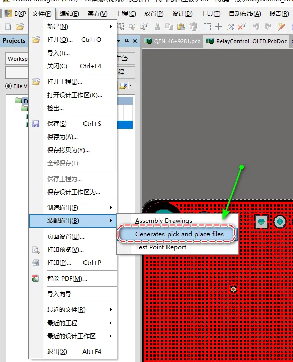
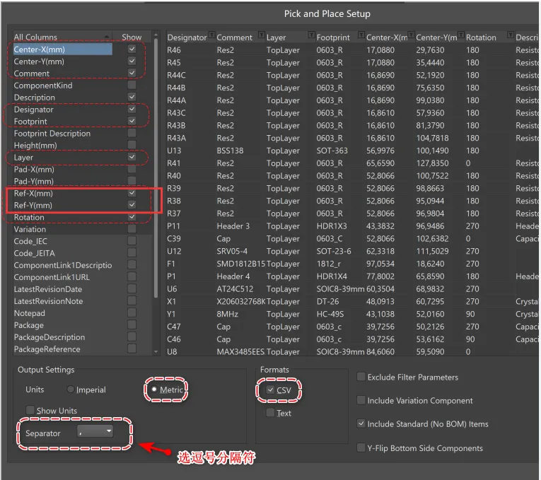
export methods for altium designer
the following solid-red mark is must-pick
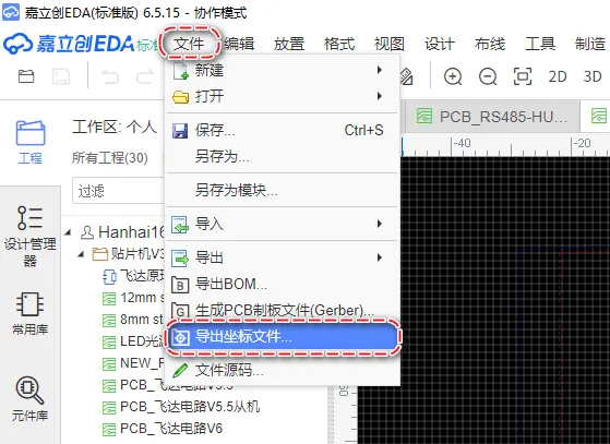
export methods for LC EDA