battery-LFP-20S-dat == 64V
battery-LFP-15S-dat == 48V
battery-LFP-4S-dat == 12.8V
Build
| Cells | Configurations |
|---|---|
| 16 | 48V 15A |
| 20 | 60V 15A |
| 24 | 72V 15A |
| 32 | 48V 30A |
| 40 | 60V 30A |
| 48 | 72V 30A, 48V 45A |
| 60 | 60V 45A |
| 72 | 72V 45A |
pack 32140
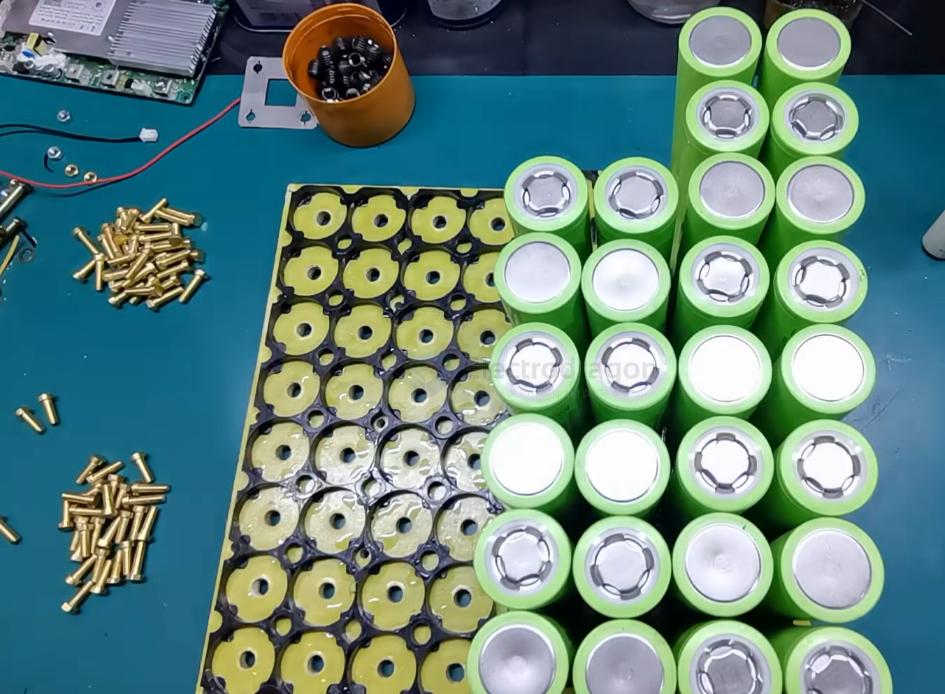

pack design
4x4
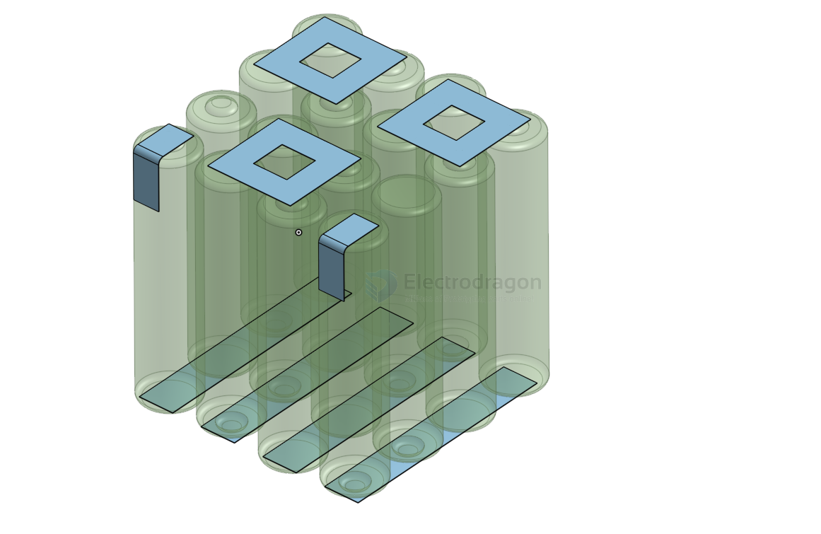
4x8 or 4x10
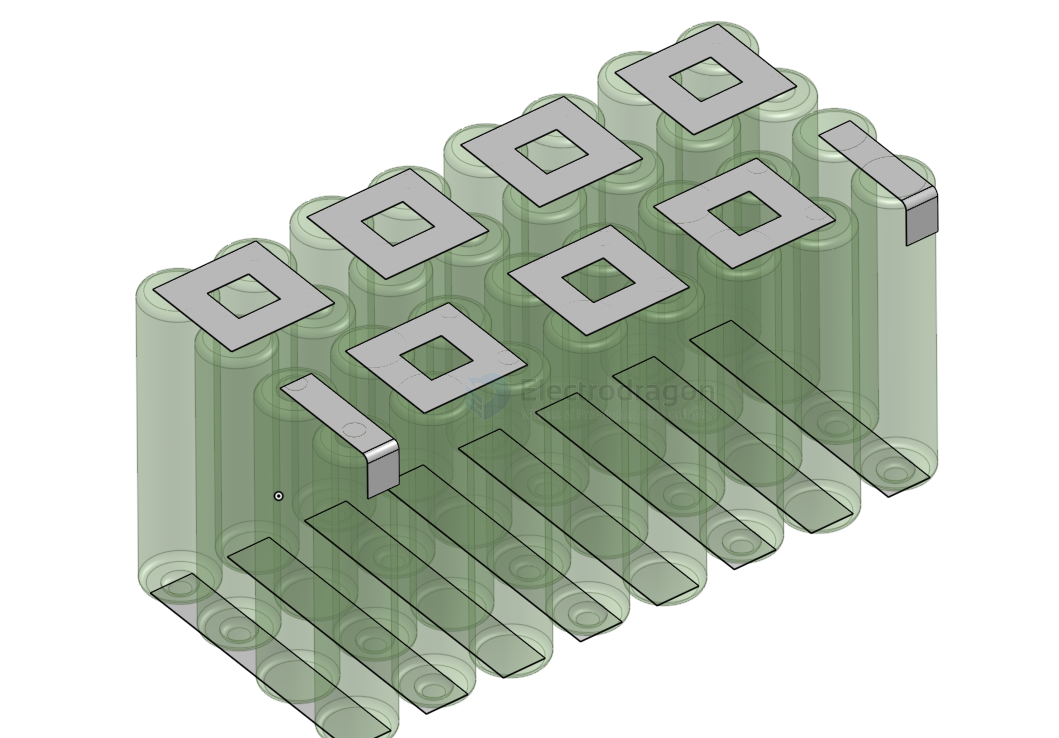
4x8 == 48V 30A
16S
1. Voltage Specifications Matrix
Because LFP voltage profiles shift based on charge state and current load, configurations must align with the three primary operational thresholds:
| Parameter State | Per Cell Threshold | Total 16S Pack Voltage | Engineering & BMS Logic |
|---|---|---|---|
| Maximum Charge Cut-off | 3.65 V | 58.4 V | Absolute high-voltage ceiling. BMS must trip if any single cell touches 3.65V. |
| Nominal Rating | 3.20 V | 51.2 V | Standard baseline used for calculating pack system capacity (Wh = Ah × 51.2V). |
| Discharge Cut-off (Empty) | 2.50 V | 40.0 V | Absolute low-voltage floor. BMS must disconnect loads to prevent copper plating/permanent damage. |
2. Resting Voltage vs. State of Charge (SoC)
Due to the characteristic flat discharge curve of $LiFePO_4$ chemistry, open-circuit voltage (OCV) remains highly stable throughout the mid-range of capacity. The following values reflect a settled, resting 16S pack (no load, no charge for at least 30 minutes):
- 100% SoC: ~54.4 V to 56.0 V (Surface charge dissipates rapidly down from 58.4V once charging terminates)
- 90% SoC: ~53.3 V
- 70% SoC: ~52.5 V
- 50% SoC: ~51.5 V
- 30% SoC: ~51.3 V
- 10% SoC: ~50.4 V (The curve begins its sharp downward knee here)
- 0% SoC: 40.0 V to 44.0 V (Voltage drops off a vertical cliff under load)