use guide
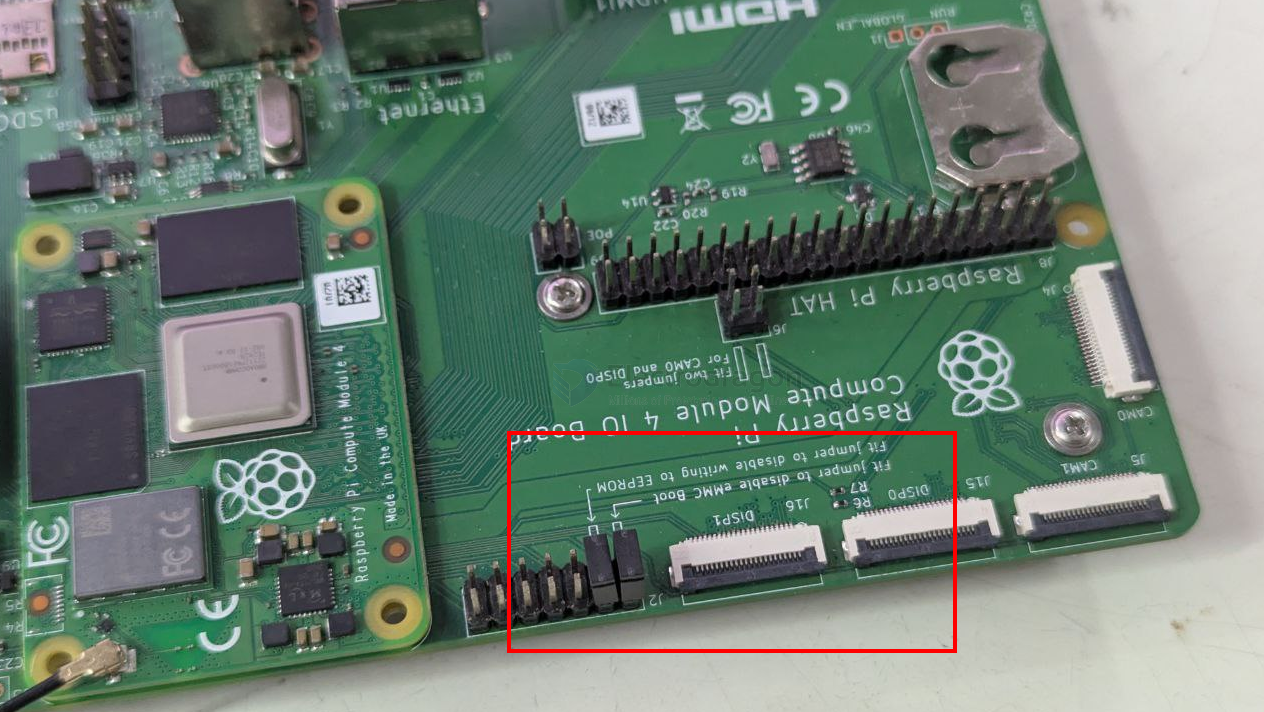
set jumper to boot
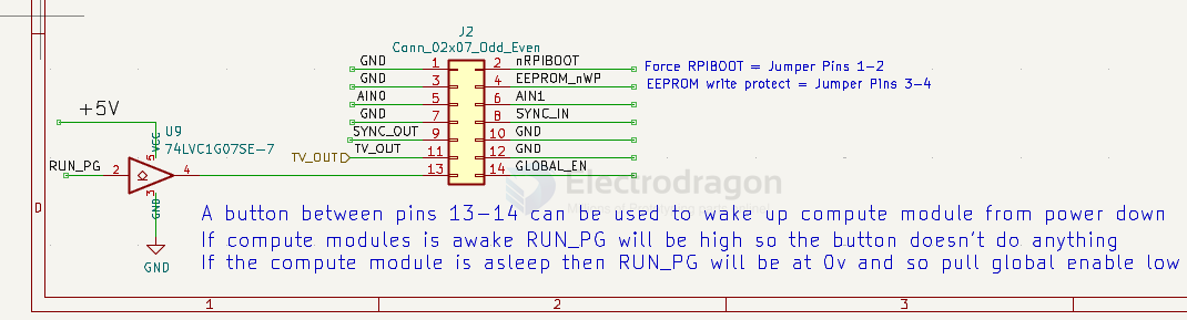
Force RPIBOOT = Jumper Pins 1-2
EEPROM write protect = Jumper Pins 3-4
BCM2711-dat boot
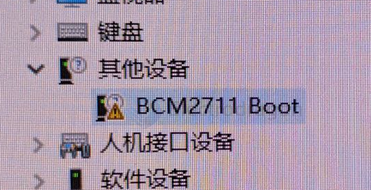
power-dat by 12V and USB-dat connected

jumpers
boot mode
| nRPIBOOT | boot | USB_SEL | USB |
|---|---|---|---|
| high | normal | high | USB-HOST-dat |
| Low | BCM2711-dat BOOT | low | USB-OTG-dat |
hardware
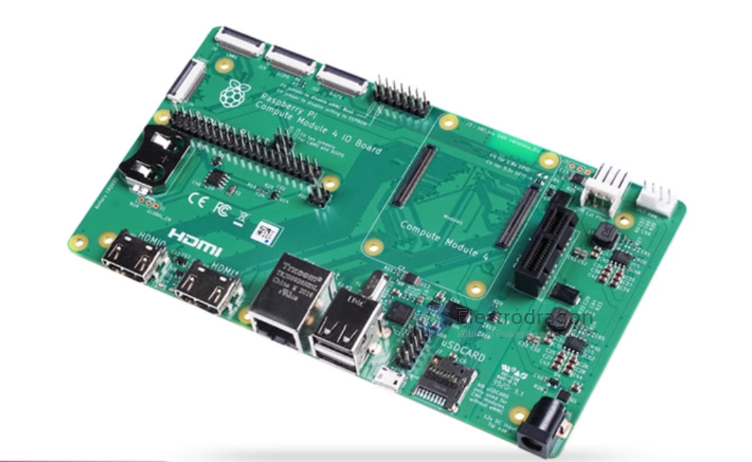
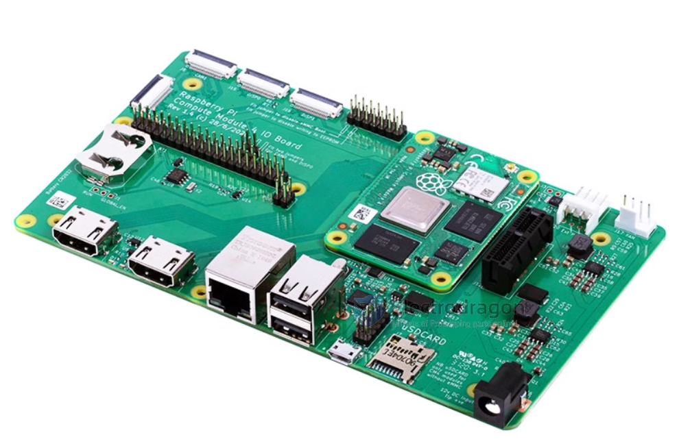
Expansion Board
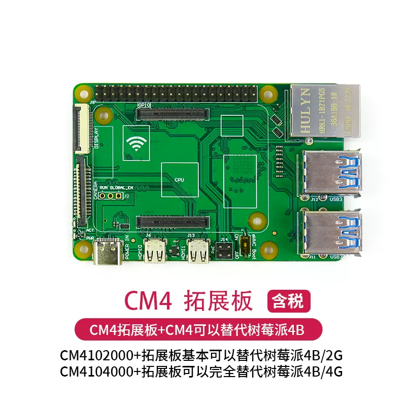
IO Expansion board
diagram
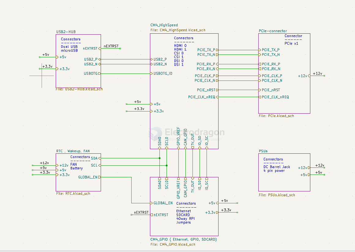
- USB2_HUB
- nEXTRST
- USB2_P
- USB2_N
- USBOTG
- CM4_HighSpeed
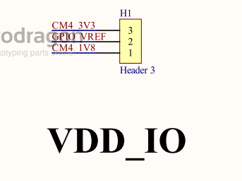
- GPIO_VREF
- CAM_GPIO
- TV_OUT
- ID_SD (cam/display)
- IS_SC (cam/display)
- PCIe-connector
- RTC, wakeup, fan
- SDA
- SCL
- global_EN
- CM4_GPIO
- GPIO_VREF
- CAM_GPIO
- TV_OUT
- ID_SD (cam/display)
- IS_SC (cam/display)
PSUs
Functions
- nRPIBOOT = pin 93 = raspbian-os-dat
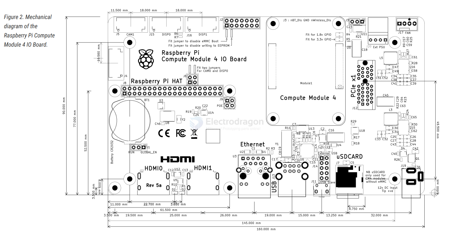
RPI CM4IO Board
- full scale large size image - https://pi4j.com/1.3/images/pi4j-rpi-cm4-header.png
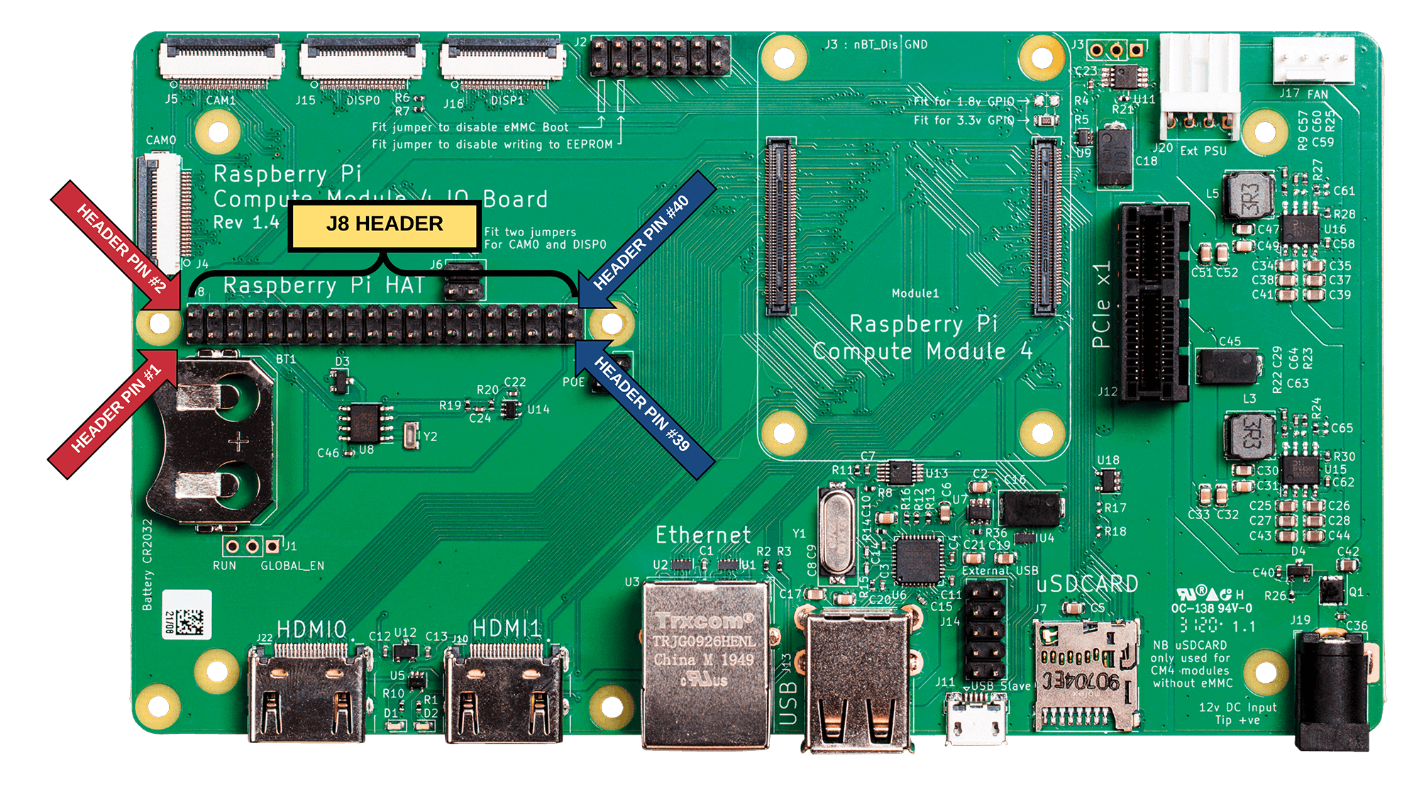
Variation Board
RPI-CM4-POE
RPI-CM4-POE_4G
RPI-CM4-Base_ETH2
- RPI-CM4-NANO
RPI-CM4-Base_B
minimum carrier board
- Small carrier board for Raspberry Pi CM4 - mincab
- Minimal_carrier_board_for_CM4
periperal
network ethernet-dat
misc fan-driver-dat
power supply dcdc-down-dat
USB USB-switch-dat - type-c-dat - USB-hub-dat
VDDIO
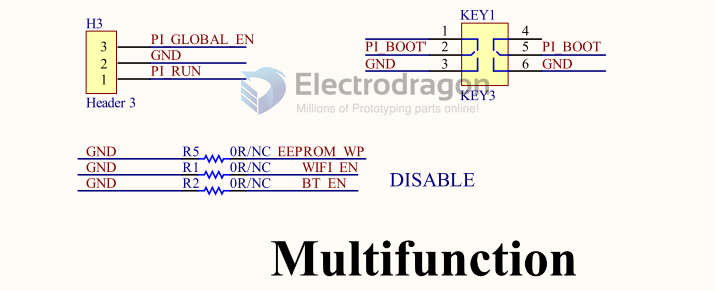
- Mode select
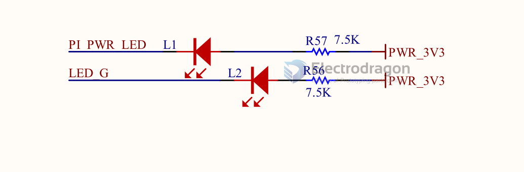
- LEDs
board note
- Board thickness : 1.56mm
- Finished copper weight inners : 1oz
Finished copper weight outers : 1oz
Board finish : OSP
- Material type : FR4
- Colour of solder resists : Green
- Colour of silk screens : White Only on the top side
- Board to : UL94-V0
TG >=130
50R trace width 0.13mm@ 3GHz
- 90R diff pair width 0.147 spacing 0.253mm @ 2.5GHz
100R diff pair width 0.127 spacing 0.253mm @ 2GHz
on board SDCARD slot == NB uSDCARD only used for CM4 modules without eMMC
jumpers
- GND - nRPIBOOT == Fit jumper to disable eMMC Boot
- GND - EEPROM_nWP == Fit jumper to disable writing to EEPROM
- J3 - GND - BT_nDis == Fit jumper to disable Bluetooth
J2
- A button between pins 13-14 can be used to wake up compute module from power down
- If compute modules is awake RUN_PG will be high so the button doesn't do anything
- If the compute module is asleep then RUN_PG will be at 0v and so pull global enable low
ref
official clone - https://oshwlab.com/stateblood/compute-module-4