Chip Info
Hardware Design Note
- Board AC Mains is be NOT isolated.
- Better use optical-coupler to send isolated signal to your MCU.
- MCU better use seperated power supply to HLW8012.
other note
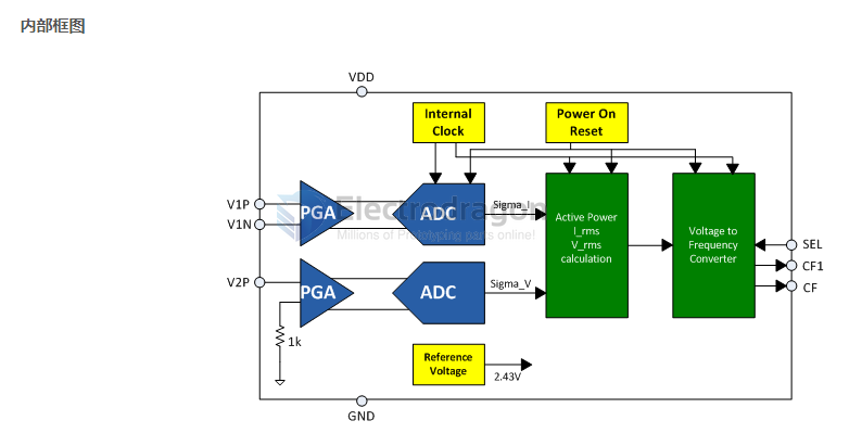
- Built-in crystal, 2.43V voltage reference source and power monitoring circuit
- 5V single power supply, operating current less than 3mA
Application
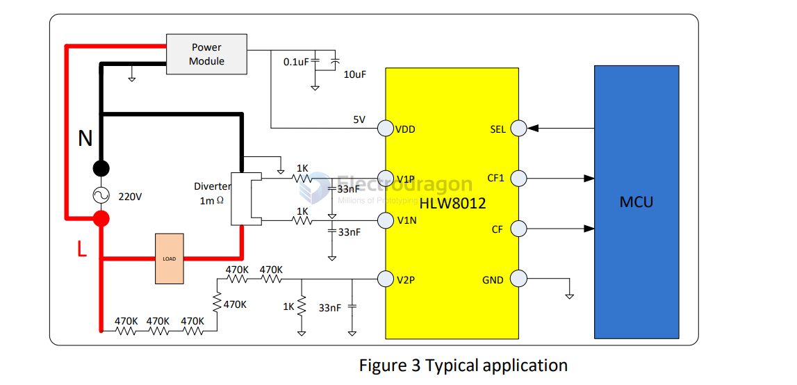
As shown in Figure 3, the power supply the HLW8012 should be in parallel with two small capacitors to filter out the noise from the grid.
- The signal of current channel is provided by the current diverter.
- The signal of voltage channel is provided by the resistor network.
CF, CF1, SEL connect to the input port of the MCU. MCU measure the pulse periods of CF and CF1, then calculate the active power, current RMS and voltageRMS
Sample resistor
- Sample Resistor is 0.002R, 2mR (diameter 2.5mm, rate current is 20A. space is 10mm, height 7.5mm, "door" shape).
Calculatoin
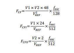
F_cf  = (V1xV2x48)/(V_ref)^2 x (F_osc/128)
F_cf1 = (V1x24)/(V_ref)      x (F_osc/512)
F_cfu = (V2x2)/V_ref         x (F_osc/512)
Note
- Fcf = Power, Fcf1 = current, Fcfu = voltage
- V1: Voltage signal on the current channel pin
- V2: Voltage signal on voltage channel pin
- Fosc: built-in crystal, the typical frequency of about 3.579MHz;
- Vref: built-in reference source, the typical voltage is 2.43V
Use with ESP8266
- The demo code will monitoring the power, current, voltage and frequency, you can monitor it via telnet to see remote debug output, same as serial output, but safe when AC main power connected.
- Pin definition to esp8266 please see the comments in sketch
- Also can calibrate the parameters, see the comments in sketch
- Enter SSID and password in the sketch, run the demo code first to see IP address
-
Connect to AC main power, login remotely via telnet, in windows for example, command: telnet 192.168.0.100
- Demo code here
Demo
https://www.youtube.com/watch?v=0aiuwRB8Uic
DS
ref
Boards - OPM1126-dat