- legacy wiki page - https://w.electrodragon.com/w/Serial
Usage
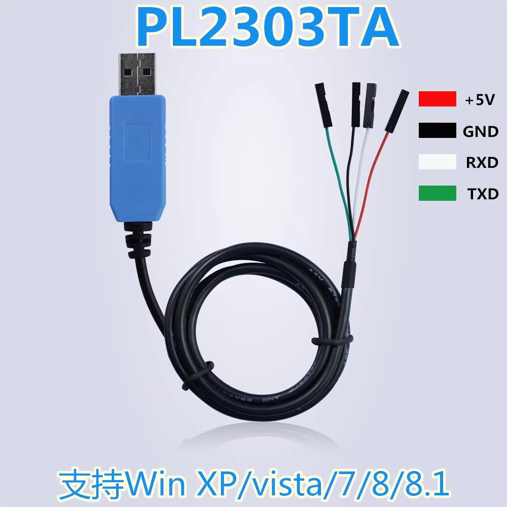
from the perspective of the cable to the perspective of the target
- Green = TXD -> target RXD
- White = RXD -> target TXD
- Red = VCC -> target +5V
- Black = GND - > target GND
Product links
- PL2303TA - DPR1041-dat
-
PL2303HX - https://w.electrodragon.com/w/PL2303HX
-
CH340 - DPR1042-dat - DPR1039-dat
-
CP2102 - DPR1003-dat, DPR1005-dat
-
FT232RL - DPR1029-dat
- 4x channels - DPR1120-dat
Use case
programming for ESP32 or ESP8266 :
- TXD -> RXD
- RXD -> TXD
- 5V -> 5V
- GND -> GND.
Booting Mode select
       Hold down IO0 button, and connect power supply to enter into flash  mode
do NOT Hold down IO0 button, and connect power supply to enter into normal mode
- please note for ESP32-C3-dat, the programming mode select pin is (button) IO9
Programming Wiring
- for NWI1126-dat

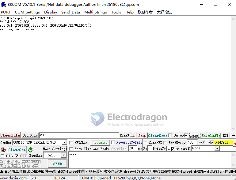
Confirm selected Mode
- The COM port monitor used below is com-monitor-dat
- if your actions are all correct, the module should enter into correct module, and print output as below
- In this mode, you can close the monitor, and further programming it with other SDK like arduino-esp32-dat
troubleshooting checklist
- reverse TX RX in case wrong wiring of communication
Applications
Flash target MCU microcontroller

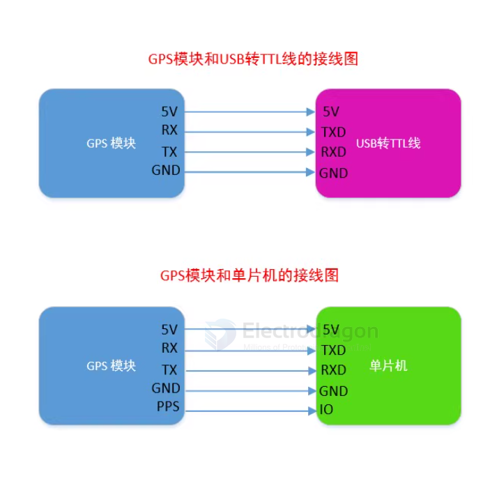
communicate with GPS module
FTDI FT232RL programming arduino pro mini

Programming STM32

- STM32-dat - ISP USART
- BOOT0 should be pull to high, foce chip into system memory
- Flash loader demostrator from official ST = Flasher
- https://www.st.com/en/development-tools/flasher-stm32.html


Compatibility
replaceable
other interface
Circuits
ref
software com-monitor-dat