https://www.electrodragon.com/product/esp32-can-rs-485-wire-interface-shield/
Main functions:
- general load switching - high-side-driver-dat
- current driving capability is ~ 36V 5A
- RS485 communication - rs485-dat
- CAN communication - can-dat
- DC-DC buck regulator - 8201 in dcdc-dat
- ESP32 core control - stack dev boards in ESP32-dat
Used ESP32-DevKitC Pins
UART2 (CAN UART)
- IO23 = CAN0_TX
- IO22 = CAN0_RX
UART1 (RS485)
- IO17 = TXD1
- IO16 = RXD1
UART0 (default used by USB-TTL bridge chip)
- TXD0 = TXD0
- RXD0 = RXD0
MISC
- IO33 = Power_ADC
- IO5 = LED
General load switching
- please note one chip is not soldering default in case you don't need two to save cost
- try IO12 or IO19
- VBAT pin up to 36V, and OUTA or OUTB will be on/off when you digitalWrite it high or low
- IO12 = CTRL1
- IO19 = CTRL2
- IO13 = STATUS1
- IO18 = STATUS2
| L_assigned | left | right | R_assigned |
|---|---|---|---|
| en | 23 | TXD2 (can) | |
| 36 | 22 | RXD2 (can) | |
| 39 | TXD0 | TXD0 (USB) | |
| 34 | RXD0 | RXD0 (USB) | |
| 35 | 21 | ||
| 32 | gnd | ||
| Power_ADC | 33 | 19 | CTRL2 |
| 25 | 18 | STATUS2 | |
| 26 | 5 | LED (prog) | |
| 27 | 17 | TXD1 (485) | |
| 14 | 16 | RXD1 (485) | |
| CTRL1 | 12 | 4 | |
| gnd | 0 | ||
| STATUS1 | 13 | 2 | |
| 9 | 15 | ||
| 10 | 8 | ||
| 11 | 7 | ||
| +5V | 6 |
Schematic of peripherals

Dimension and pin definitions

- Red pins for power supply
- blue pins for serial interfaces
- green pins IO22/IO23 for CAN BUS
-
the rest green pins and orange pins for power switch controls
- back side selector for UART-0-main or UART1-alternative
removing tips
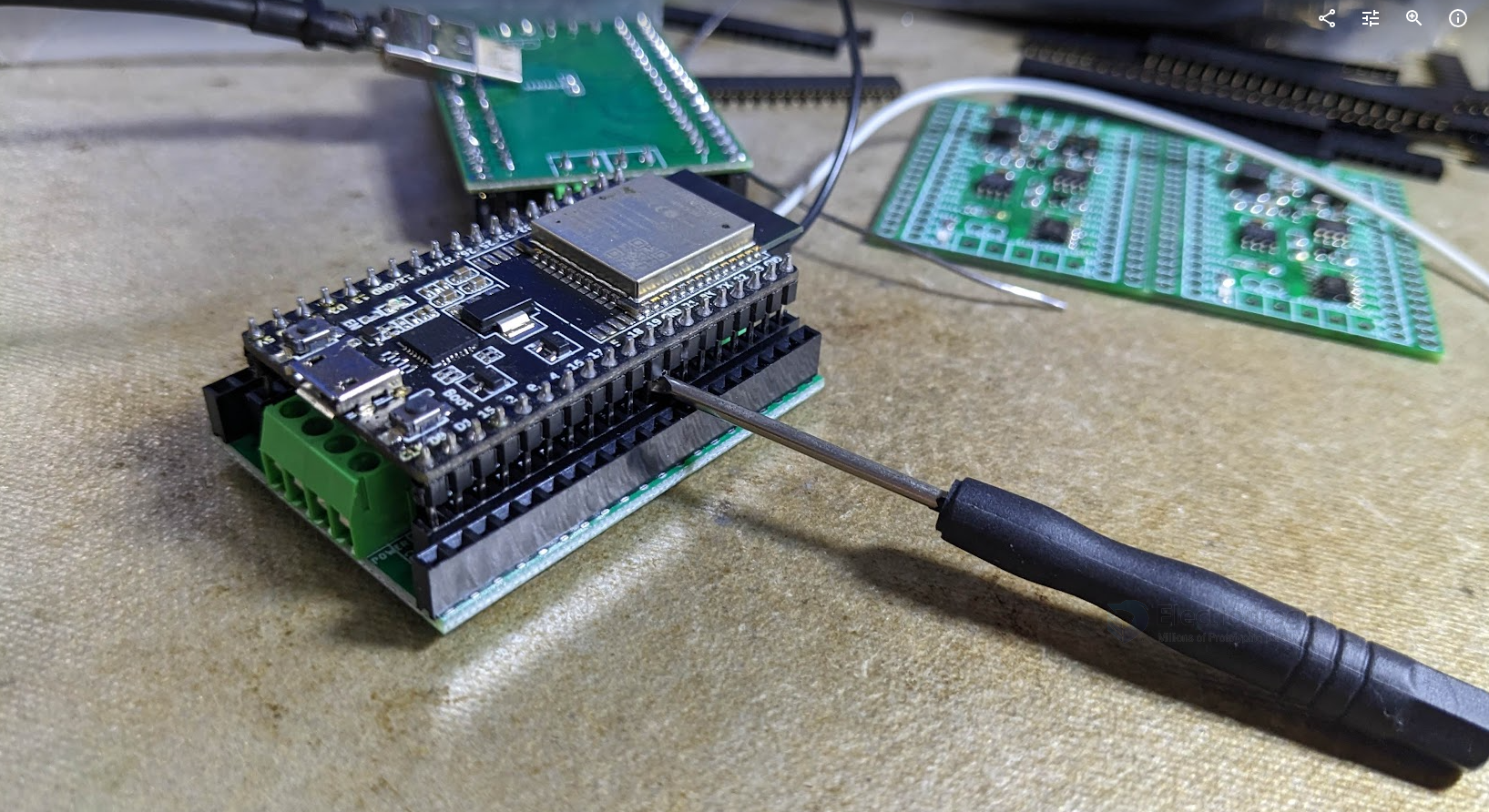
- use a small driver to leverage in the between carefully
demo
- function test method: https://www.youtube.com/shorts/vkFrkTkw5Ak
-
demo code look into our arduino-dat - git-dat
-
https://www.youtube.com/shorts/TeaZ1xKcAqg
- tested work with DPR1103-dat
Update logs
V1.11
- notice boards are using new KF2EDG-dat connector from 2024 Aug.
- add one power supply indicator led
ref
- code please refer to our ESP32 arduino github repository
- https://github.com/Edragon/Arduino-ESP32/tree/master/BSP/NWI1245/power-switch-test
- https://github.com/Edragon/Arduino-ESP32
-
https://github.com/Edragon/Arduino-ESP32/blob/master/Sketchbook/interface/RS485-1/RS485-1.ino
- NWI1245 - NWI1245-QC-log-dat