First version please see here. MPC1073-dat
Features of MPC1119
- Remove the right chip to free extra GPIOs of P2 chain, optionally
- bended-angle direction of the chain output
- Connect PIN4 or PIN8 to E_BUF for E-line
- Power input and output from the left large pin connectors, with power protection
- removed memory and RTC functions
pin definitions
- pin definitions please refer to page - RMP-driver-dat
The following two GPIOs are not used at all and free:
- pin SC to raspberry pi pin ID_SC
- pin SD to raspberry pi pin ID_SD
Extra pins Used by Chain P3:
- to use the extra pins, you need to cut the jumpers to release them from the chip below, and chain P3 can not be used anymore.
Debug Port:
-
RX GND (some boards mark could be reversed): UART_RX debug, or ROW_E set to ground
Wiring
- If you supply power to matrix panels separately, the converter board MPC1119 will be power supplied by pins, no need extra power supply.
- If you supply all power from one port on the converted board, you can connect the power supply to matrix panels from another port.
- Voltage should be no more than 5.5V.
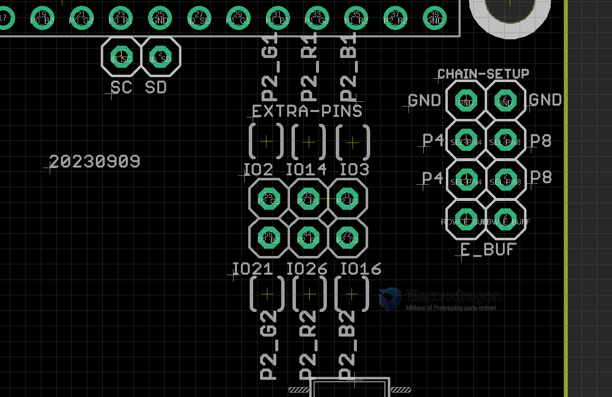
Extra Pins
- Please note there is a wrong typo on the board, IO12 should be IO14
- top pins: IO2 IO12 IO3
- bottom pins: IO21 IO26 IO16
Legacy Wiki
-
RMP Guide - https://w.electrodragon.com/w/RPI_RMP_Guide#P3/P464x64(tested)
E-line Setup, Extra GPIOs Pin Definitions
Setup E-line, PIN4 to E, PIN8 to GND or vice vese.

P2 (Chain-3) 5V logic output pin definitions
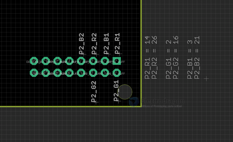
P2 pins definitions, 3V3 direct lead out