Info
product url - Wireless NRF24 Controlled Relays Arduino Shield
refer for more demo code in legacy wiki page here: - legacy wiki page
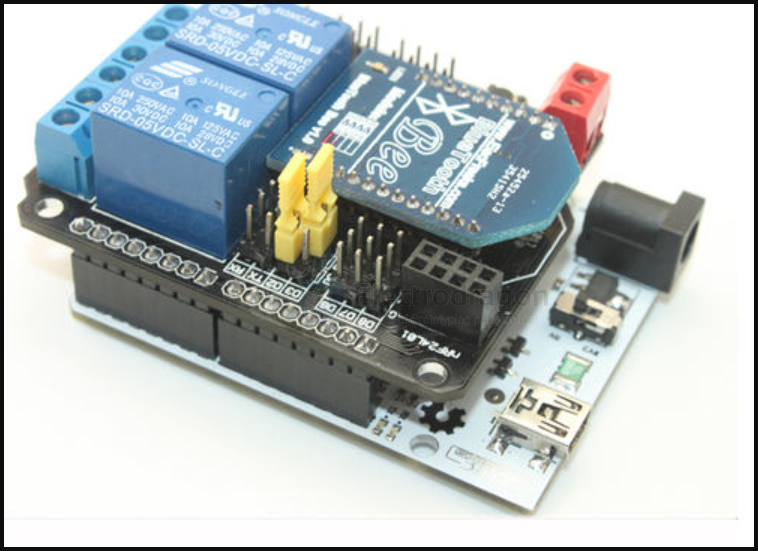
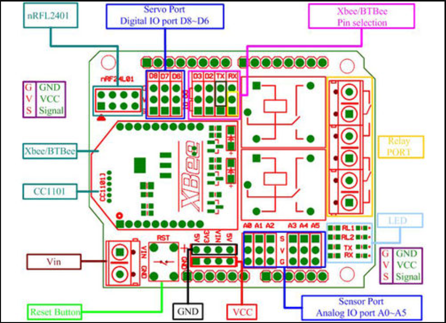
Board Map, Dimension, Pins, chip info, Use Guide, Setup Jumper, etc.
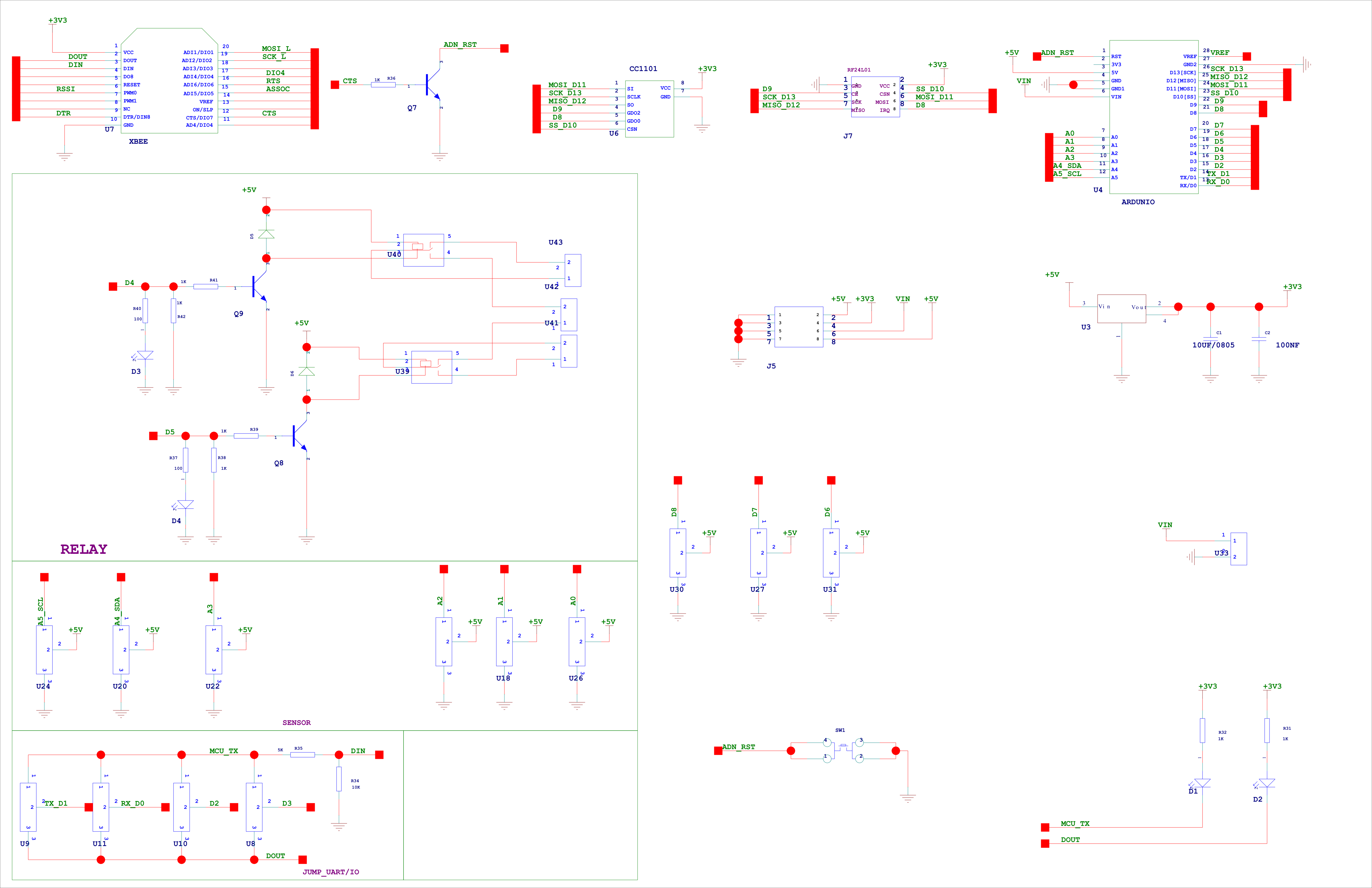
SCH
Applications, category, tags, etc.
- network-dat - xbee-dat - btbee-dat - nrf24l01-dat - CC1101-dat - sensor-dat
Demo Code and Video
The demo code is test the module RF, BTBee and Relay part. And the code base on the NRF24L01-dat, you need change the pin define as below. If you test the Bluetooth Bee interface, you need used other Bluetooth device paired with BTBee.
Here we used a Android phone with our bluetooth-dat as client to paired with BTbee(HC-o6).
#include "API.h"

//---------------------------------------------
#define TX_ADR_WIDTH    5
// 5 unsigned chars TX(RX) address width
#define TX_PLOAD_WIDTH  1
// 20 unsigned chars TX payload
//---------------------------------------------
#define CE       9
// CE_BIT:   Digital Input     Chip Enable Activates RX or TX mode
#define CSN      10
// CSN BIT:  Digital Input     SPI Chip Select
#define SCK      13
// SCK BIT:  Digital Input     SPI Clock
#define MOSI     11
// MOSI BIT: Digital Input     SPI Slave Data Input
#define MISO     12
// MISO BIT: Digital Output    SPI Slave Data Output, with tri-state option
#define IRQ      8
// IRQ BIT:  Digital Output    Maskable interrupt pin
//*********************************************
#endif