Normal direction and force distribution
This is a fluid‑statics + structural mechanics question. Conclusion first, details after.
1) Hydrostatic pressure itself: no difference
For a flat surface and for a curved surface (at the same depth h):
p = ρ g h
Pressure depends only on depth, not on shape. The pressure magnitude per unit area is identical for a given depth.
The difference is not in the pressure magnitude, but in the local normal directions and how the pressure vectors combine.
2) Difference in normal directions (the key point)
-
Flat surface
- The entire face has a single fixed normal direction.
- All pressure vectors point the same way.
- Resultant force = pressure × area (single direction).
- Example: observation windows, flat end caps.
-
Curved surface (cylinder)
- Each small surface element has its own normal direction.
- Local pressure always acts along the local surface normal (radial inward for a cylinder).
- Example: pressure hulls, submarine shells.
3) Resultant force and stress consequences
-
Cylinder sidewall
- Radial pressure components around the circumference largely cancel each other.
- Net lateral resultant ≈ 0.
- Principal stresses produced are hoop (circumferential) stress and axial stress (if end caps are present).
- Therefore cylinders are very resistant to external hydrostatic pressure.
-
Flat plate
- All pressure vectors add in the same direction.
- The resultant force accumulates and causes bending, bulging, or fracture.
- Flat faces are typically the weakest parts of pressure designs.
4) Intuitive picture
- A flat plate feels like it is being "pushed" inward by a block of water.
- A cylinder feels like it is being "squeezed" evenly from all sides; the water "hugs" it rather than pushes it off.
shape design summary
Conclusion (same internal volume):
| Shape | Surface area | Stress concentration | Pressure efficiency |
|---|---|---|---|
| Flat box | Largest | Very high | ❌ Worst |
| Cylinder | Medium | Low | ✅ Good |
| Sphere | Smallest | Almost none | ✅✅ Best |
For the same internal volume, the rounder the shape, the more depth a given amount of material can resist.
Acrylic (PMMA) hemispherical container for 100 m depth
Summary and key engineering recommendation
- Design safety factor: multiply theoretical thickness by 4–6.
- Example: 2.2 × 5 ≈ 11 mm
- Conclusion (ready-to-use): For a 130 mm diameter hemispherical acrylic (PMMA) viewport at 100 m depth:
- Recommended thickness: 10–12 mm
- Absolute minimum (not recommended): 8 mm
Flat window comparison
- Under the same conditions, a flat acrylic window would require 25–30 mm thickness or more and still carries a risk of sudden brittle fracture.
- A hemispherical window is approximately 3–5× stronger than a flat window.
Practical construction advice (important)
- Use a single-piece thermoformed hemisphere (do not bond halves together).
- Do not glue the hemisphere in place.
- Use an O-ring with a floating clamping arrangement; avoid rigid clamping.
- Make the inner diameter slightly larger than the outer diameter seating to prevent the window being "pulled out" by differential pressure.
One-line summary
For a 130 mm diameter hemispherical acrylic viewport operating at 100 m depth, 10–12 mm thickness is a reliable, engineering-grade, safe choice.
Metal cylinder with transparent end windows (100 m target)
Context: If the pressure vessel is a metal cylinder and the two ends are transparent acrylic observation windows, at 100 m depth (≈10 bar / 1.0 MPa external pressure) the failure mode shifts from cylinder buckling to transparent end-window deflection and seal failure. Below are practical, engineering-focused parameter recommendations that include an overall safety factor of ≈2.
Overall conclusions
- A metal cylinder easily reaches 100 m and even 300 m.
- The real limiting factor is the transparent acrylic end windows.
- To reliably reach 100 m, the windows must be: thick, spherical or domed, and sealed with a face (axial) O-ring.
Recommended standard design (most robust — strongly recommended)
This is a common, engineering-grade approach for 100 m observation housings. It is simple and has a high success rate.
Cylinder (main pressure hull)
- Material: 6061-T6 aluminum or 304 stainless steel
- Outer diameter: 200 mm
- Wall thickness:
- Aluminum: 4–5 mm
- Stainless steel: 3 mm
- Length: 600 mm
- Construction: minimal welds or full welds with annealing
-> For 100 m this provides a large strength margin.
Transparent end windows (critical)
- Material: cast acrylic (PMMA)
- Shape: outward convex hemisphere / spherical cap (not flat)
- Diameter: ≈180–190 mm (embedded)
- Minimum thickness: 20 mm
- Effective radius of curvature: ≥ 90 mm
- Loading behavior: external pressure clamps the dome and improves sealing as depth increases.
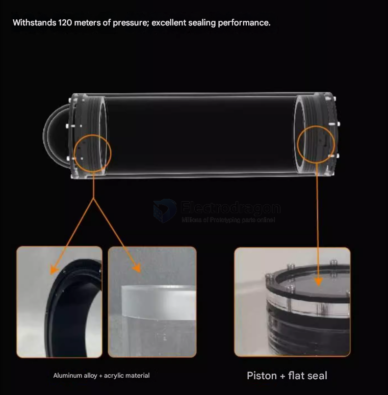
Sealing
- O-ring material: NBR or FKM
- Hardness: 70–75A
- Compression: 20–25%
- Sealing style: axial face seal (recommended); radial seals are not recommended
- Window mating surfaces: chamfered and polished (Ra ≤ 0.8)
Engineering assessment
- Theoretical window pressure capacity: ≈200 m
- Recommended operational depth (with safety margin): 100–120 m for long-term service
Secondary (lower-risk) option (higher risk, but lighter)
- Window material: acrylic
- Shape: shallow dome
- Thickness: 15–18 mm
- Constraints:
- Window diameter ≤ 160 mm
- Use dual O-rings
- Use a metal clamp ring to load the window evenly
This may reach 100 m for short-term use but is not recommended for repeated long-term operation.
Absolutely unacceptable end-window options (will fail at 100 m)
- Flat acrylic windows (no matter the thickness)
- Transparent windows ≤ 12 mm thick
- Large-diameter (≥ 180 mm) flat windows
- Gluing the window directly (no mechanical seal)
- Unsupported "clamped glass" without metal backing
Quick risk summary (100 m class)
- Cylinder structural strength: ★★★★★ (very safe)
- Transparent window risk: ★★★★★ (the single critical item)
- Seal failure risk: ★★★☆☆ (controllable)
- Manufacturing tolerance importance: ★★★★★
One-sentence version
Metal cylinder + thick domed acrylic observation windows = standard engineering approach for 100 m.
Recommended parameters: metal cylinder 4–5 mm wall + 20 mm domed acrylic end window + O-ring face seal.
General pressure design notes
Using tubing for deep water
If you need to reach 100 m underwater, follow these recommendations:
- Industrial thick-wall PVC (PN16 or higher) can be used, but plastics are still not recommended for deep external pressure environments.
- Use a flange connection with an O-ring seal — this is far superior to bonded joints.
- Using a metal pipe (e.g., 316L stainless steel) is more reliable.
Most important note: Never rely on plastic adhesives for deep-water pressure seals. Always use mechanical sealing (flanges + O-rings), metal housings, or purpose-built deep-water equipment.