chain gear Sprocket
chain types
| Chain / Model | Pitch (in) | Pitch (mm) | Internal Width (W) | Avg. Tensile Strength | Typical / Best Use Case |
|---|---|---|---|---|---|
| Bicycle Standard (410 / 415) | 1/2" | 12.70 | — | — | Standard bicycles, most electric bike motors |
| #25 (1/4") | 1/4" | 6.35 | 3.18 mm | ~4,000 N | Small, high-speed motors; miniature robotics |
| T8F (8 mm) | — | 8.00 | 4.80 mm | ~6,000 N | Heavy-duty scooters; higher-torque small drives |
| #35 (3/8") | 3/8" | 9.525 | 4.77 mm | ~9,500 N | Go-karts, high-power motors, heavy-load DIY |
Notes:
- Pitch is the most critical parameter — chain and sprocket must share the same pitch to mesh correctly.
- Inner width (W) and tooth thickness must match or be compatible with the sprocket.
1/2" Circular Pitch (CP) / #40 Sprockets
If the gear is designed for a 1/2" spacing (common in ANSI #40 roller chains or 1/2" CP spur gears), the following tooth counts are industry standards:
| Category | Common Tooth Counts ($N$) |
|---|---|
| Small (Drive/Pinion) | 9, 10, 11, 12, 13, 14, 15 |
| Medium (Idler) | 16, 17, 18, 19, 20, 24, 25 |
| Large (Driven) | 30, 32, 35, 40, 48, 54, 60, 72 |
main specs
- 06B
- 08B
specs
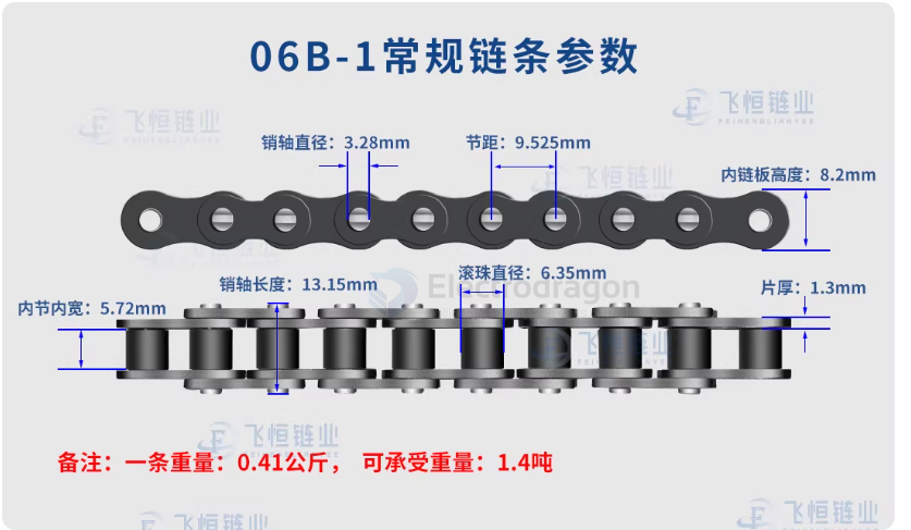
1. Chain — Main Parameters
| Parameter | Description | Unit / Example |
|---|---|---|
| Pitch (p) | Distance between adjacent roller centers | mm (e.g., 12.7, 15.875) |
| Roller Diameter (d₁) | Roller outer diameter | mm |
| Inner Width (b₁) | Inner width between chain plates (sprocket tooth fit) | mm |
| Chain Length | Total number of links × pitch | mm |
| Plate Thickness | Determines load capacity | mm |
| Tensile Strength / Rated Load | Maximum allowable tension the chain can carry | N or kN |
| Type / Series | Standard or series (ANSI, ISO, DIN, light/medium/heavy) | e.g., ANSI 40, DIN 08B-1 |
⚠️ Pitch is the most critical parameter. The chain and sprocket must have the same pitch to mesh correctly.
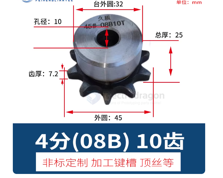
2. Sprocket — Main Parameters
| Parameter | Description | Unit / Example |
|---|---|---|
| Number of Teeth (z) | Sprocket tooth count; determines gear ratio | 10–120 teeth |
| Pitch (p) | Must match the chain pitch | mm |
| Tooth Profile Standard | Defines the tooth shape for proper engagement | ANSI, ISO, DIN |
| Outside Diameter (OD) | Useful for layout and clearance calculations | mm |
| Mounting Bore / Pin Hole Diameter | Sprocket mounting for shaft or bolts | mm |
| Thickness / Tooth Width | Must be compatible with chain inner width | mm |
| Material / Strength | Determines wear resistance and load capacity | Steel, cast iron, aluminum alloy |
⚠️ Tooth count and sprocket diameter set the drive ratio but do not affect mesh compatibility as long as the pitch is the same.
3. Key Fit and Selection Points
- Pitch match: The chain pitch must match the sprocket pitch exactly.
- Inner width: Sprocket tooth width must be less than or equal to the chain inner width.
- Profile standard: Chain and sprocket standards (ANSI, ISO, etc.) must match to avoid poor engagement and premature wear.
- Minimum sprocket tooth count: Too few teeth increases bending fatigue on the chain; typically choose ≥ 12 teeth when possible.
- Mounting alignment: Shaft diameter, keyway, and bolt pattern must match the sprocket mounting method.
chain modify
To modify a chain for a bike, you need a specific tool called a Chain Breaker.
1. Opening the Chain
First, identify if your chain has a Master Link (a link that looks different and is designed to be removable).
Method A: With a Master Link
- Action: Use master link pliers (or needle-nose pliers) to squeeze the two pins together.
- Result: The side plates will slide and unlock, allowing the chain to pull apart.
Method B: Without a Master Link (Standard Link)
- Action: Place any link into the Chain Breaker tool.
-
Process: 1. Align the tool's driving pin with the chain rivet (pin).
- Turn the handle to push the rivet out.
- Important: If you intend to reuse the pin, do not push it all the way out. Leave it hanging slightly on the outer plate.
2. Modifying the Length (Shortening)
To make the chain fit your specific motor-to-wheel distance:
- Measure: Wrap the chain around your Drive Wheel (motor) and Driven Wheel (rear hub) to determine the required length.
-
Determine the Cut Point: * If using a Master Link: Both ends of the chain must be Inner Links.
- If joining via a Pin: One end must be an Inner Link and the other an Outer Link.
- Remove Links: Use the chain breaker to push the pins out completely on the excess section of the chain.
3. Reconnecting the Chain
- Threading: Guide the chain through your frame and over the sprockets.
-
Joining:
- Using a Master Link: Insert the two halves from opposite sides and pull the chain apart until you hear a "click."
- Using a Pin: Use the chain breaker to push the pin back through the links until it is centered.
- Fixing Stiff Links: If the connection point is stiff, gently bend the chain sideways at that joint to "set" the plates and ensure smooth rotation.