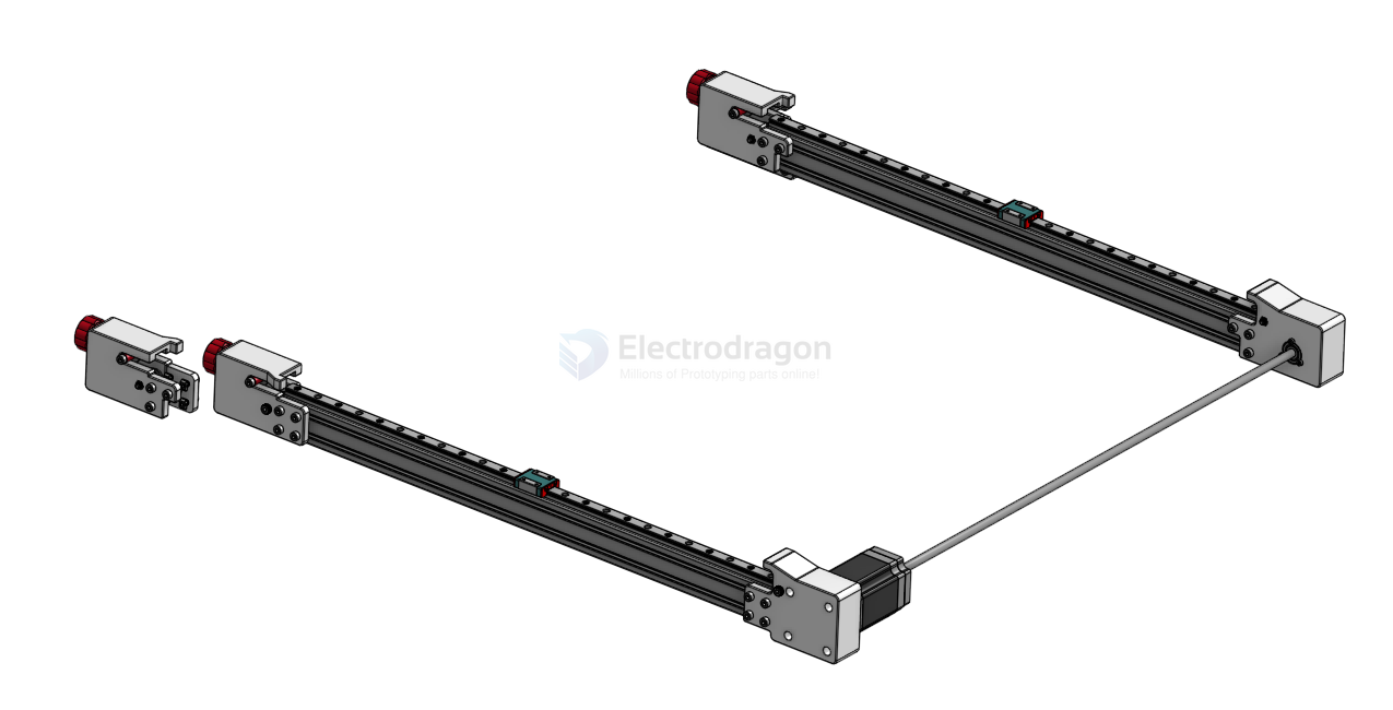
3D View
Tension Slider Assembly BOM List
| Category | Part_Name | Part Description | Quantity |
|---|---|---|---|
| Nuts and Bolts | Hex_Screw_M5x35mm | Tensioning Screw for Belt Tension | 3 |
| 3D Printed Part | Star_Knob_Base | - | 3 |
| 3D Printed Part | Star_Knob_Cover | - | 3 |
| Standard Part | GT2_Idler_20T_5B_6mm | - | 3 |
| Nuts and Bolts | M5_Nut | - | 6 |
| Nuts and Bolts | Socket_Cap_Screw_M5x45mm | - | 3 |
| 3D Printed Part | Tension_Slider | Tensions the Belt | 3 |
Standard Part GT2_Idler_20T_5B_6mm == timing-pulley-dat
Nuts and Bolts
- Hex_Screw_M5x35mm
- M5_Nut - nut-dat
- Socket_Cap_Screw_M5x45mm
3D Printed Part - 3d-print-service-dat
- Star_Knob_Base == star_knob v7 == https://cad.onshape.com/documents/ff9d1e3bb0c6648192bdf385/v/70ff96265c3a5c65e5e93ef9/e/10f29c1435693a48f4ed55a7
- Star_Knob_Cover == can not find this file
- Tension_Slider == https://cad.onshape.com/documents/e640485c664452ef18221338/v/ecf6a991a8286a17a6f28085/e/1d506c43d62b8f4e412e0560?renderMode=0&uiState=67d019d4668a6a59b71b9bf7
steps by steps
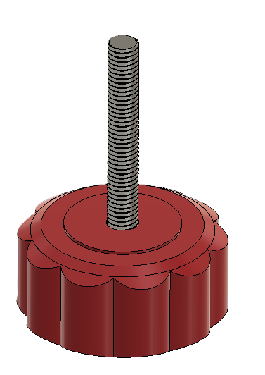
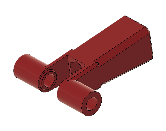
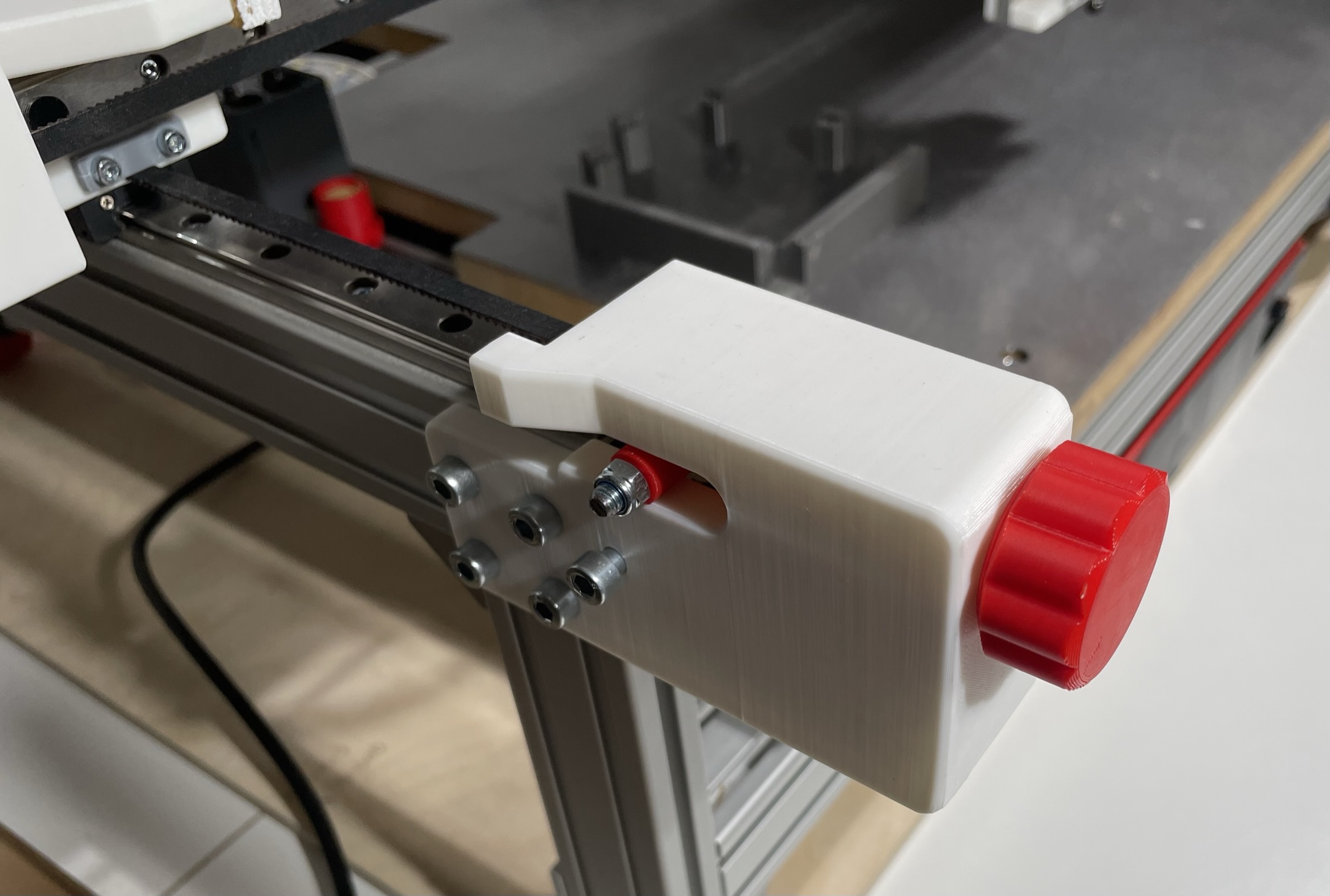
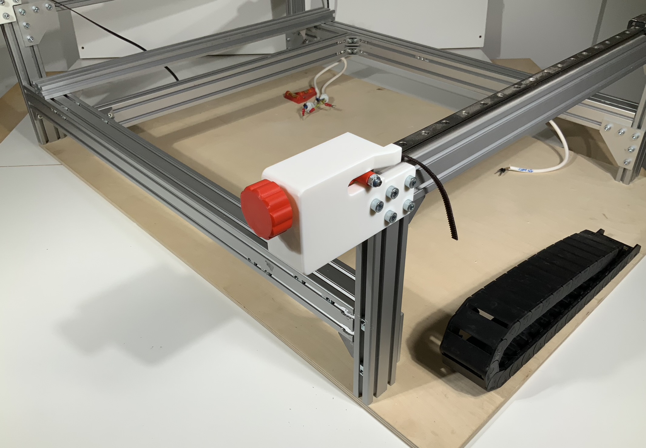
Tension Slider
The Tension_Slider tensions the belt on the X-Axis and Y-Axis. In total three are needed in the machine. The Hex_Screw_M5x35mm is pressed into the Star_Knob_Base and the Star_Knob_Cover glued on inorder to encapsulate the screw.
- A M5_Nut is dropped into the Tension_Slider.
- The Socket_Cap_Screw_M5x45mm is pushed through the hole of the Tension_Slider and the GT2_Idler_20T_5B_6mm and secured with a M5_Nut.
- Pass the belt through the center of the aluminum extrusion before mounting both mounting plates to the aluminum extrusion.
Y-Axis Left Back Mounting Plate
- Press and secure the 608 Bearing on the side in place with M3 screws. Socket_Cap_Screw_M3x6m
- Insert the Belt and attach the Idler to the 8mm shaft.
- Insert a M5 screw and feed the Belt around the Idler and secure the screw with a nut.
- Mount the Y-Axis_Left_Back_Mounting_Plate to the Aluminum extrusion with M5 screws.
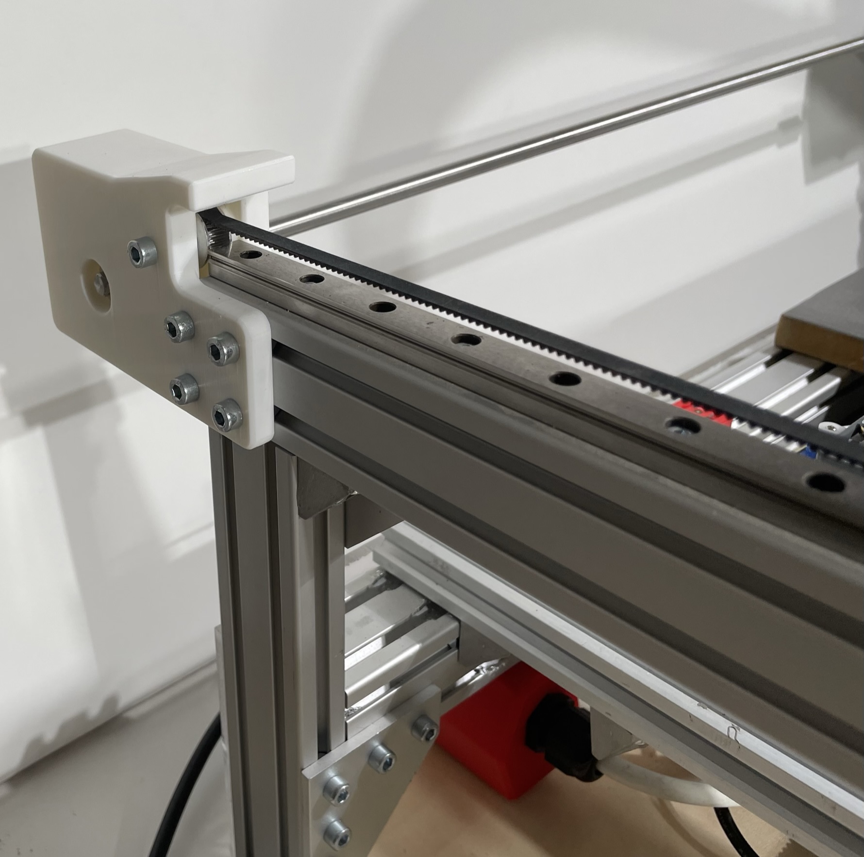
Y-Axis Front Mounting Plates
- Insert the Belt and attach the Idler with a M5 screw and nut.
- Insert the Tension_Sliderand feed the Belt around the Idler.
- Mount the Y-Axis_Front_Mounting_Plate to the Aluminum extrusion with M5 screws.
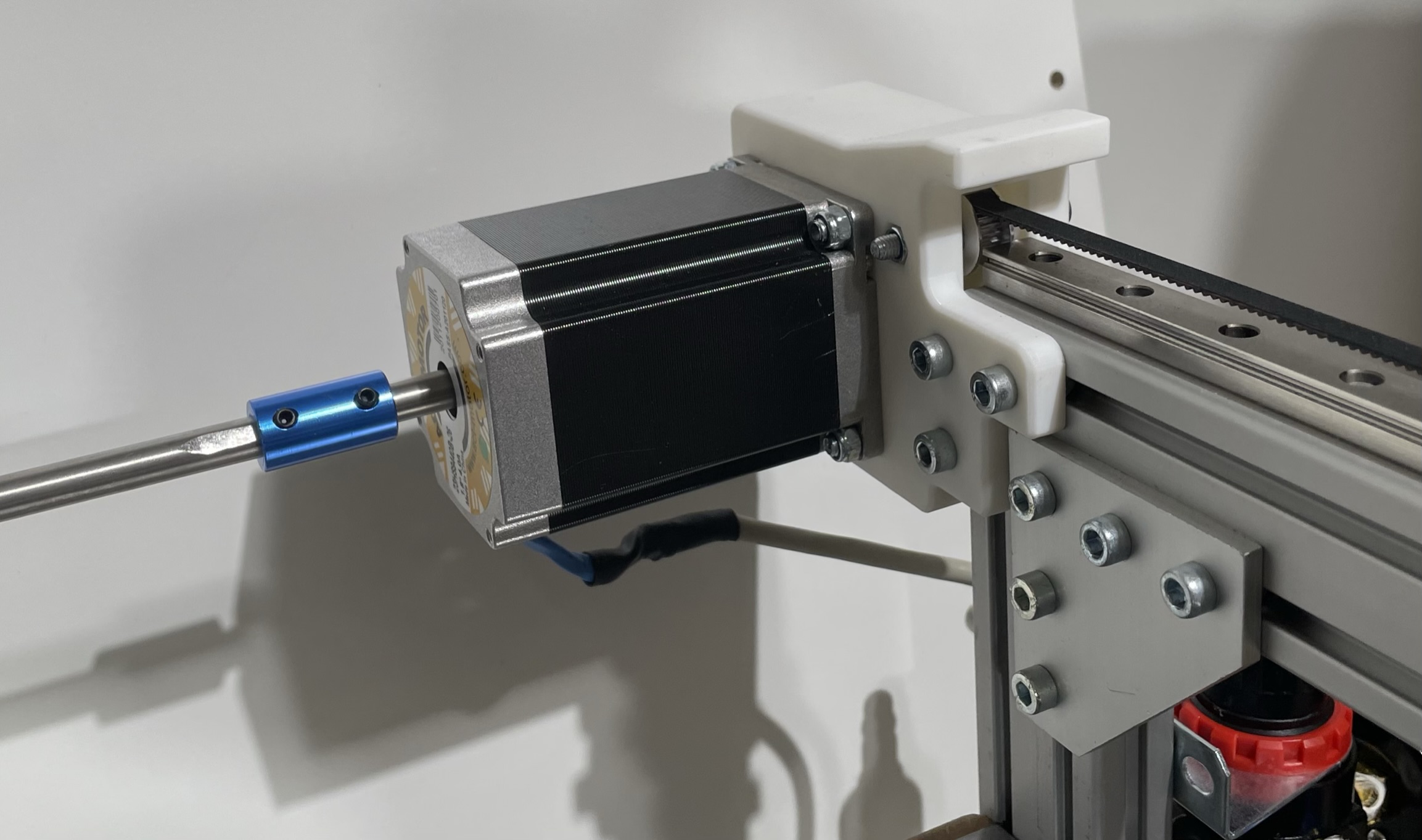
Y-Axis Right Back Mounting Plate with motor
Connect the Pulley to the Motor shaft.
- Mount the Motor to the Y-Axis_Right_Back_Mounting_Plate with M5 screws and nuts.
- Insert the Belt and attach the Idler with a M5 screw and nut.
- Mount the Y-Axis_Right_Back_Mounting_Plate to the Aluminum extrusion with M5 screws.
- Connect the Motor Shaft and long 8mm shaft together with a motor-coupler-dat.
Y-axis
| Category | Part_Name | Part Description | Dimensions | Quantity |
|---|---|---|---|---|
| 3D Printed Part | Left_Front_Mounting_Plate_Y-Axis | - | - | 1 |
| 3D Printed Part | Right_Front_Mounting_Plate_Y-Axis | - | - | 1 |
| 3D Printed Part | Left_Back_Mounting_Plate_Y-Axis | - | - | 1 |
| 3D Printed Part | Right_Back_Mounting_Plate_Y-Axis | - | - | 1 |
| Standard Part | GT2_Idler_20T_5B_6mm | - | - | 4 |
| Nuts and Bolts | M5_T_Nut | Mounting Mounting Plates to Alu Extrusions | - | 30 |
| Nuts and Bolts | M5_Nut | Motor Mounting Nuts and Idler Mounting Nuts | - | 6 |
| Nuts and Bolts | Socket_Cap_Screw_M5x12mm | Mounting Mounting Plates to Alu Extrusions | - | 30 |
| Nuts and Bolts | Socket_Cap_Screw_M5x40mm | Holding the Idle in place | - | 2 |
| Standard Part | GT2_Timing_Pulley_20T_8B_6mm | Driving Pulley for Belt | - | 2 |
| Nuts and Bolts | Socket_Cap_Screw_M5x16mm | Motor Mounting Screws | - | 4 |
| Standard Part | 608_Bearing | Bearing to keep the Shaft align on the left back side | - | 1 |
| Nuts and Bolts | Socket_Cap_Screw_M3x6mm | Mount Bearing Screws | - | 3 |
| Standard Part | Nema23_Motor - stepper-dat | Dual Shaft Motor Nema 23; 84mm; 2,4Nm; 8mm Dual Shaft | - | 1 |
| Standard Part | Shaft_8mm | 8mm Shaft for transfering the Motor rotation to the left side | 630mm | 1 |
| Standard Part | Shaft_Coupler_8mm | Couples the Motor Shaft to the long shaft to the left side | - | 1 |
| Standard Part | GT2_Belt_6mm | Y-Axis Belt | 1355mm | 2 |
3D Printed Part
- Left_Front_Mounting_Plate_Y-Axis
- Right_Front_Mounting_Plate_Y-Axis
- Left_Back_Mounting_Plate_Y-Axis
Right_Back_Mounting_Plate_Y-Axis
CAD images
images