understand PPM
PPM (Pulse Position Modulation)
What changes: 👉 Pulse position (timing shift)
What stays fixed:
Pulse width
Frequency (usually)
|  ■■        |  early pulse
|     ■■     |  mid pulse
|        ■■  |  late pulse
Used for
- RC receivers (classic PPM signal)
- Some communication systems
- Timing-based encoding
PPM (Pulse Position Modulation) is a type of analog signal used in radio control (RC) systems to transmit multiple channels of control information (like throttle, steering, elevator, etc.) over a single wire.
In simple terms:
- It sends a series of pulses.
- The position (or timing) of each pulse within a repeating frame represents the value for a specific channel.
- A longer "sync" pulse marks the end of one frame and the beginning of the next.
So, instead of needing a separate wire for each control channel, PPM combines them into one sequential signal.
PPM over voltage protection == PPM OVP
1️⃣ Resistor Divider + Comparator (Most Common)
Vout ──R1──┐
        ├── V_sense → Comparator → PWM inhibit
GND  ──R2──┘
2️⃣ Zener Clamp Based PPM OVP (Simple & Cheap)
Vout ──R──┬── Zener ── GND
        └──→ PWM control pin
high voltage control
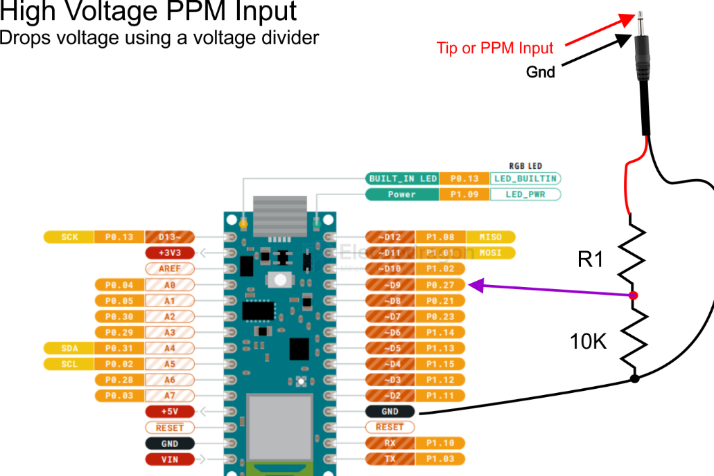
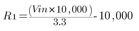
For 5V PPM signal, R1 = (5*10,000)/3.3 - 10,000 = 5151ohms Round the value UP to the nearest commonly available resistor, which is 5600ohm or 5.6k
For 7V PPM Signal, R1 = 7*10,000/3.3 - 10,000 = 11,212 ohms ==> Rounded Up ==> 12,000ohm or 12Kohm
demo video
RC #PPM PWM send and receive at Arduino, note the four channels color
Internal control by SDR1064-dat
Wfly #PPM console control toy rover