DP2358
- datasheet == Chip-dat/depuw-dat/1451_DP2358-electrodragon.pdf
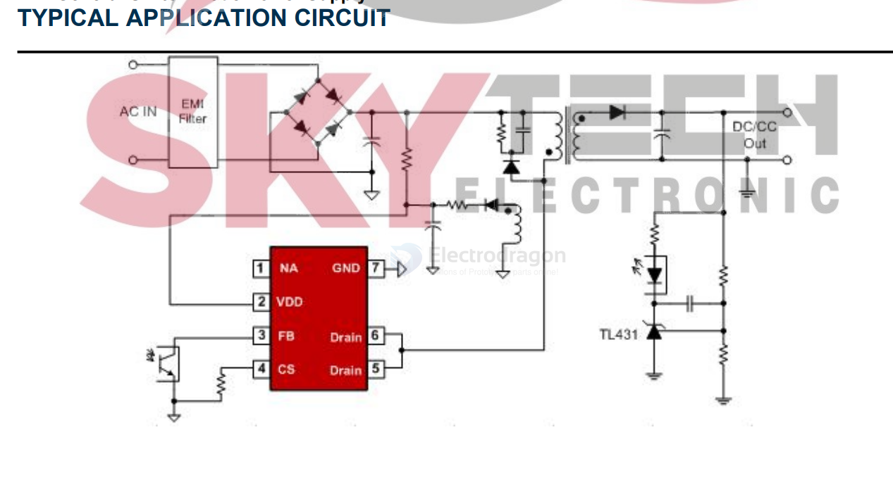
Pin Description
- Pin 1 (NA): Un-connection Pin. Left float in the practical design
- Pin 2 (VDD): PIC power supply pin
- Pin 3 (FB): Feedback pin. The loop regulation is achieved by connecting a photo-coupler to this pin. PWM duty cycle is determined by this pin voltage and the current sense signal at Pin 4
- Pin 4 (CS): Current Sense Input Pin
- Pin 5, 6 (Drain): The Power MOSFET Drain
- Pin 7, 8 (GNDP): The Ground of the IC