⚙️ Mode 2: Monostable (One-shot Pulse)
example 1. 🔁 Triggered pulse of fixed length
🔧 Wiring:
 VCC
  |
 [R1]
  |
 Pin 7 (DIS)
   |
  Pin 6 (THR) ------+
                   |
                  [C1]
                   |
                  GND

- Button → Pin 2 (TRIG), pulled up to VCC
- Pin 4 (RESET) → VCC
- Pin 5 (CTRL) → 0.01µF to GND
- Pin 3 = Output
🧮 Pulse Time:
T = 1.1 × R1 × C1example 2. 🧠 Circuit Function: Monostable Pulse Generator (One-Shot Timer)
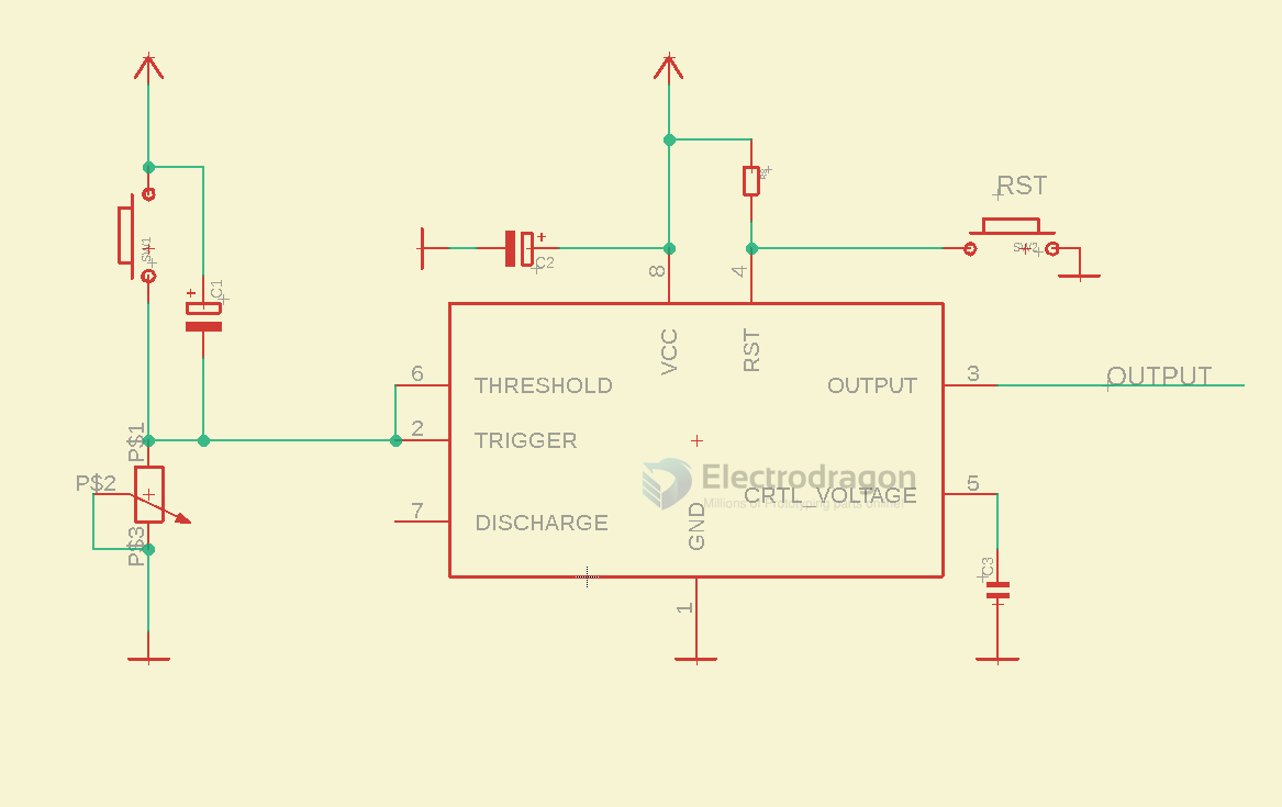
🔍 What it does:
- When the button is pressed (SW1), the circuit triggers the 555 timer to generate a single output pulse.
- The duration of the pulse is set by the resistor PS1 (a potentiometer) and capacitor C1.
- The output pin (pin 3) goes high (ON) for a fixed time, then returns low automatically.
🔁 How it Works (Step-by-step)
-
Initial state:
- The 555 timer waits for a low signal on the Trigger (pin 2).
- The output (pin 3) is normally LOW.
-
Trigger event:
- When SW1 is pressed, the capacitor C1 pulls the Trigger pin (2) low.
- This activates the 555 timer.
-
Timing begins:
- Output (pin 3) goes HIGH immediately.
- The capacitor C1 starts charging through the potentiometer (PS1).
-
Pulse duration:
- The high output duration
Tis determined by:T = 1.1 × R × C Where: R = resistance of PS1 (in ohms) C = capacitance of C1 (in farads)In your case:- PS1: adjustable potentiometer
- C1: 47µF → So T is adjustable via the pot.
- The high output duration
-
End of timing:
- Once the capacitor reaches 2/3 of Vcc, the timer resets itself.
- Output (pin 3) goes LOW again.
🧩 Other Components:
| Component | Role |
|---|---|
| C2 | Power filter cap for stability |
| C3 | Controls pin noise on control voltage (pin 5) |
| PS2 | Potentiometer for fine adjustment of trigger |
| SW2 | Reset switch → forces timer to stop |
✅ Typical Use Cases:
- Delay timer
- Pulse stretcher
- Debouncing a switch
- Timer for lights, relays, buzzers
- Generating single-shot triggers for digital logic