legacy wiki page - https://w.electrodragon.com/w/LM386
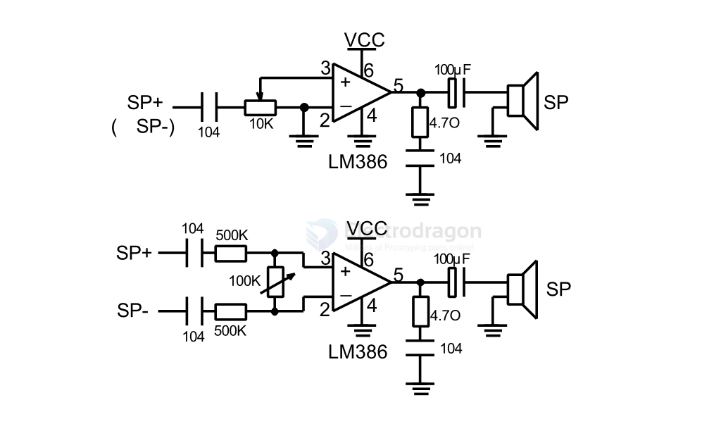
SCH
| gain | R4/RPI1 (pot-trim) | R1 | C1 | C2 |
|---|---|---|---|---|
| 10x | 10K | - | - | - |
| 14x | 5K | - | - | - |
| 20x | 2K | - | - | - |
| 50x | 1.2K | 10uF | 10UF | |
| 100x | ? | 10uF | 10UF | |
| 200x | 0 | 10uF | 10UF |
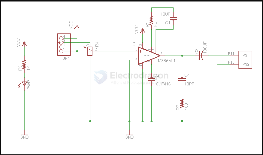
SCH
SCH 4
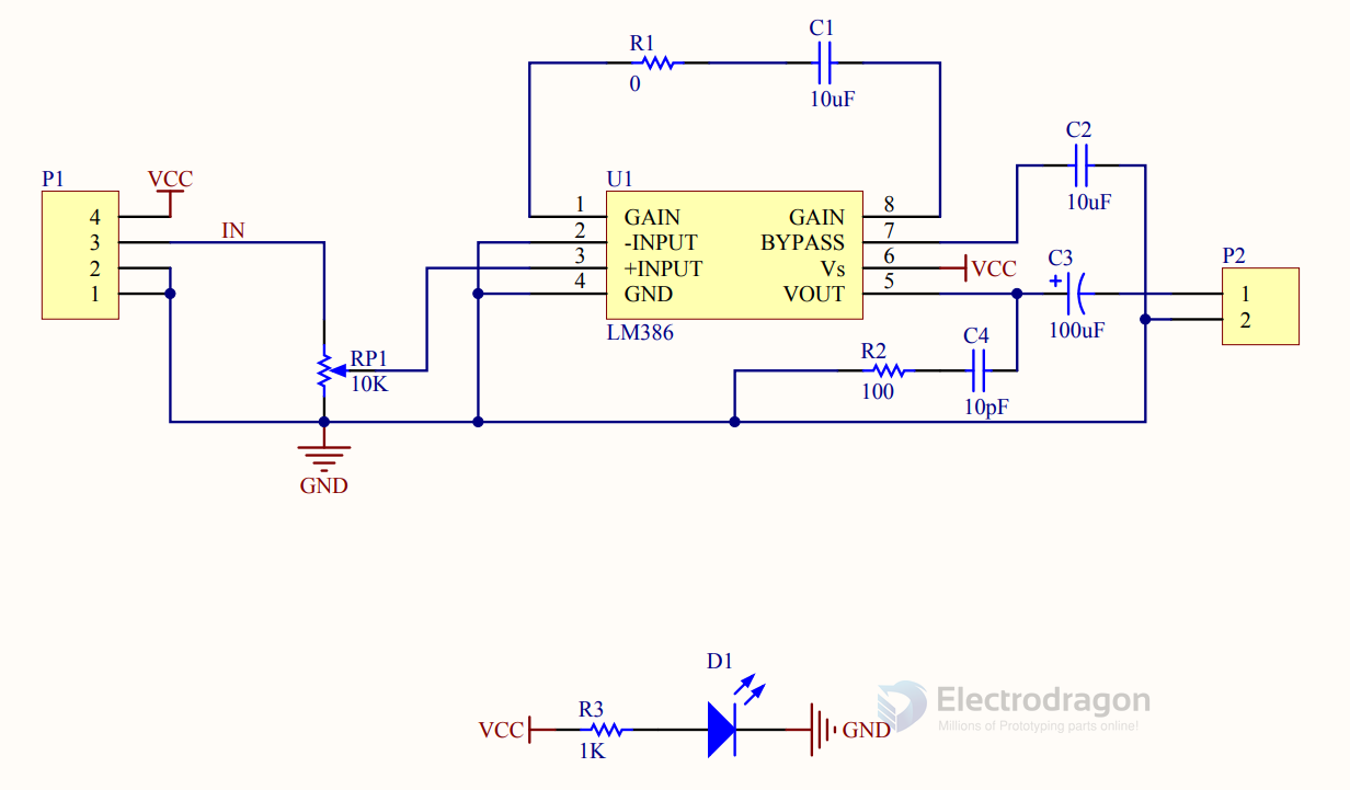
SCH 3
LM386 with microphone, Amplification is controlled by R2 in schematic 2
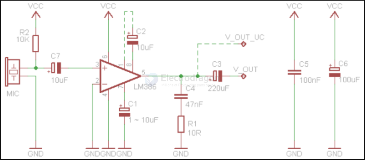
| BOM | value | explain |
|---|---|---|
| C1 | 1~10uF | Bypass capacitor |
| C2 | 10uF | Gain 200x. Optional, without 10uf is 20x gain. |
| C3 | 220uF | Output coupling capacitor |
| C4 | 47nF | Boucherot cell |
| C5 | 100nF | Power supply decoupling |
| C6 | 100uF | Power supply decoupling |
| C7 | 10uF | Microphone coupling capacitor |
| MIC | Electret microphone | |
| R1 | 10R | Boucherot cell |
| R2 | 1 ~ 10K | Microphone load resistor |
| VSS | 4 ~ 12V | Supply voltage |
demo code
Only generate very simple sound for testing.
#define SOUNDOUT_PIN 9

void setup(void){
//Set the sound out pin to output mode
pinMode(SOUNDOUT_PIN,OUTPUT);
}

void loop(void){
//Generate sound by toggling the I/O pin High and Low
//Generate a 1KHz tone. set the pin high for 500uS then
//low for 500uS to make the period 1ms or 1KHz.

//Set the pin high and delay for 1/2 a cycle of 1KHz, 500uS.
digitalWrite(SOUNDOUT_PIN,HIGH);
delayMicroseconds(500);

//Set the pin low and delay for 1/2 a cycle of 1KHz, 500uS.
digitalWrite(SOUNDOUT_PIN,LOW);
delayMicroseconds(500);
}
online simulation
- https://www.circuitlab.com/circuit/hcqmtsvrz7mw/lm386/
- https://www.circuitlab.com/browse/by-tag/lm386/
demo
https://www.youtube.com/watch?v=Q6ArZWTh-w0&ab_channel=Electrodragon