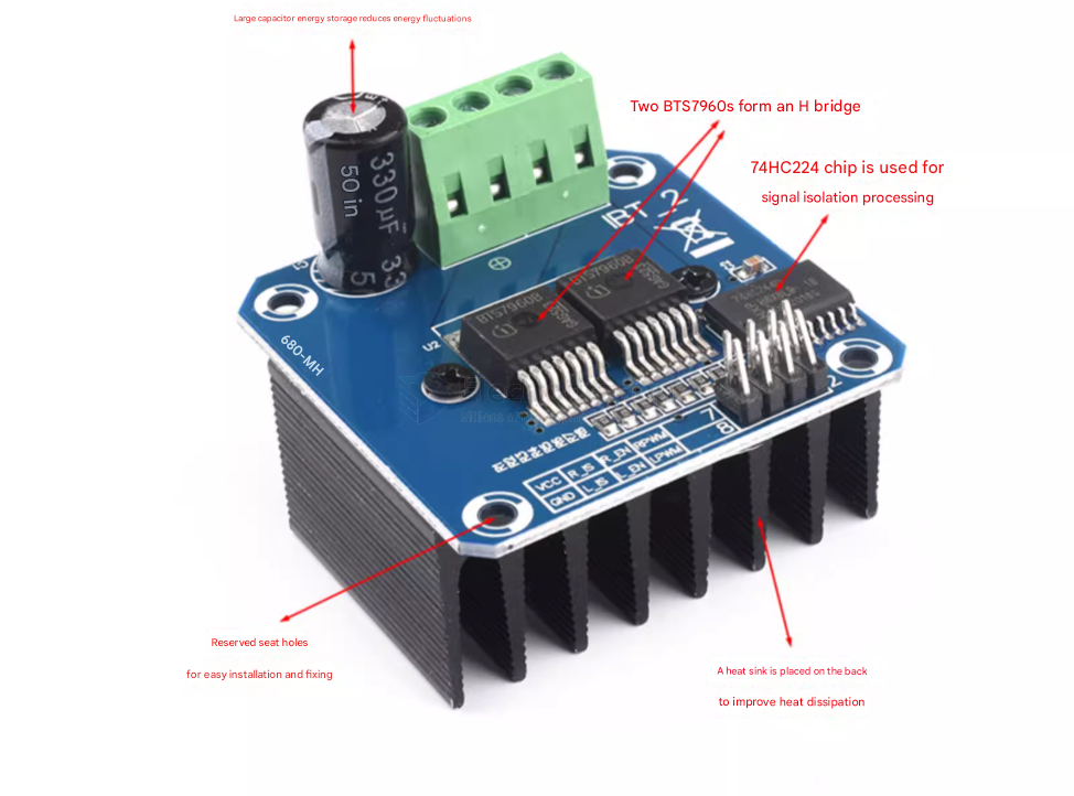
This driver uses Infineon's high-power driver chip BTS7960 to form an H-bridge driver module, featuring over-temperature and over-current protection. The dual BTS7960 H-bridge driver circuit provides strong driving and braking capabilities. It uses a 74HC244 chip to effectively isolate the microcontroller from the motor driver! High current 43A!
Product Features:
- 1. Dual BTS7960 high current (43A) H-bridge driver
- 2. 5V isolation from the microcontroller, effectively protecting the microcontroller
- 3. Capable of motor forward and reverse rotation, two PWM inputs up to 25kHz frequency
- 4. Two channels for over-current and over-temperature error signal output;
- 5. Isolated chip 5V power supply (can share 5V with the microcontroller);
- Power supply voltage 5.5V to 27V;
Model: EDIBT-2
- Input Voltage: 6V~27V
- Maximum Current: 43A
- Input Level: 3.3V~5V
- Control Method: PWM or Level
- Duty Cycle: 0~100%
- Current Sense Output: Yes
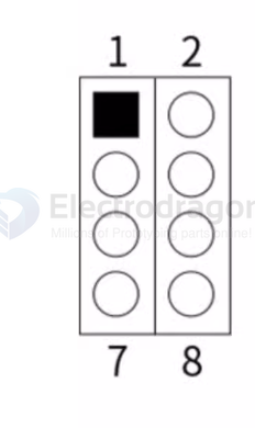
Wiring == 2x4 == 8pin
except feedback R_IS and L_IS and power supply , actual control is 4 pin
- 1. R_PWM: Forward rotation level or PWM signal input, high level active
- 2. L_PWM: Reverse rotation level or PWM signal input, high level active
- 3. R_EN: Forward rotation driver enable input, high level enable, low level disable
- 4. L_EN: Reverse rotation driver enable input, high level enable, low level disable
- 5. R_IS: Forward rotation driver side current alarm output
- 6. L_IS: Reverse rotation driver side current alarm output
- 7. VCC: +5V power input, connects to microcontroller 5V power
- 8. GND: Signal common ground
Usage Method:
Method 1:
- Connect VCC to the microcontroller's 5V power, connect GND to the microcontroller's GND.
- Short R_EN and L_EN together and connect to a 5V level; the driver can now operate.
- L_PWM: Input PWM signal or high level for motor forward rotation.
- R_PWM: Input PWM signal or high level for motor reverse rotation.
Method 2:
- Connect VCC to the microcontroller's 5V power, connect GND to the microcontroller's GND.
- Short R_EN and L_EN together and input a PWM signal for speed control.
- L_PWM: Input 5V level for motor forward rotation.
- R_PWM: Input 5V level for motor reverse rotation.
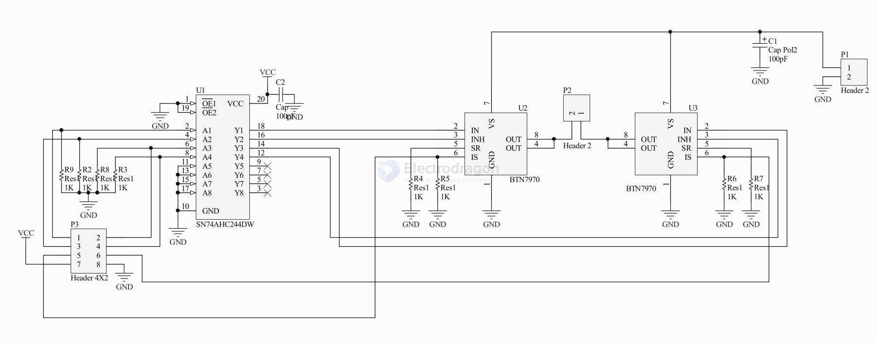
SCH
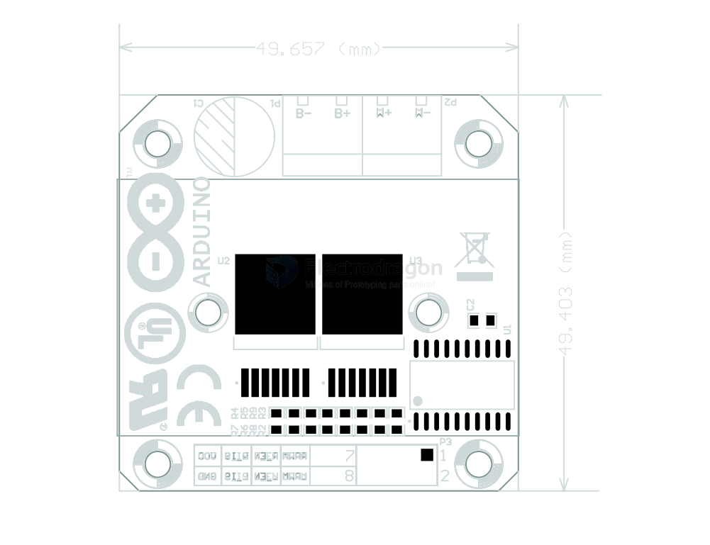
Dimension
simple arduino control code
🔌 Arduino Pin Connections (Example)
| BTS7960 Pin | Arduino Pin | Purpose |
|---|---|---|
| VCC | 5V | Logic power |
| GND | GND | Ground |
| R_EN | 8 | Enable right channel |
| L_EN | 9 | Enable left channel |
| RPWM | 10 | (PWM) Right side PWM signal |
| LPWM | 11 | (PWM) Left side PWM signal |
the demo code
// Define motor control pins
#define RPWM 10
#define LPWM 11
#define R_EN 8
#define L_EN 9

void setup() {
// Set control pins as output
pinMode(RPWM, OUTPUT);
pinMode(LPWM, OUTPUT);
pinMode(R_EN, OUTPUT);
pinMode(L_EN, OUTPUT);

// Enable both sides of the H-Bridge
digitalWrite(R_EN, HIGH);
digitalWrite(L_EN, HIGH);
}

void loop() {
// Rotate motor forward
analogWrite(RPWM, 200);  // PWM value (0-255)
analogWrite(LPWM, 0);
delay(3000);

// Stop motor
analogWrite(RPWM, 0);
analogWrite(LPWM, 0);
delay(1000);

// Rotate motor backward
analogWrite(RPWM, 0);
analogWrite(LPWM, 200);
delay(3000);

// Stop motor
analogWrite(RPWM, 0);
analogWrite(LPWM, 0);
delay(1000);
}
✅ Summary
| Feature | Description |
|---|---|
| Motor channels | 1 DC motor |
| Direction control | Yes (Forward / Reverse) |
| Speed control | Yes (via PWM) |
| Continuous current | ~30A (with proper cooling) |
| Peak current | ~43A |
| Voltage range | Typically 6V–27V |