- https://www.quectel.com/product/gnss-l76-l/
The module can be connected to a dedicated passive or an active single-band GNSS antenna in order to track the GNSS satellite signals.
-
Chip-cn-dat/quectel-dat/quectel-gps-dat/L76-dat/quectel_l76_series_hardware_design_v3-3.pdf - Chip-cn-dat/quectel-dat/quectel-gps-dat/L76-dat/L76-LB Hardware Design.pdf
-
Chip-cn-dat/quectel-dat/quectel-gps-dat/L76-dat/GNSS-EVB_SCH_V2.01_130614.pdf - Chip-cn-dat/quectel-dat/quectel-gps-dat/L76-dat/quectel_l76_series_evb_user_guide_v2-1.pdf
L76 VS L76-L VS L76-B
| model | status | systems | channels |
|---|---|---|---|
| L76K | GPS/GLONASS/BDS/QZSS | ||
| L76-L | available | GPS, GLONASS (or BDS), Galileo and QZSS | 33track/99acq |
| L76 | |||
| L76-B | available | GPS/BDS/QZSS | |
| L70 | NA | GPS + QZSS | |
| L70-R | available | GPS + QZSS |
- Chip-cn-dat/quectel-dat/quectel-gps-dat/L76-dat/Quectel_L76B_GNSS_Specification_V1.1.pdf
- L76-L supports: Additional LNA, I2C
| model | LNA | Vio | extra |
|---|---|---|---|
| L76 | x | 2.7-2.9V | |
| L76-L | y | 2.7-2.9V | I2C |
| L76-L(L) | y | 1.7-1.9V |
- L76L-M33 is L76-L. = 2.7-2.9V Vio
- L76LL-M33 is L76-L(L). = 1.7-1.9V Vio
https://forums.quectel.com/t/l76-module-naming-and-i-o-voltage-l76l-m33/22934/3
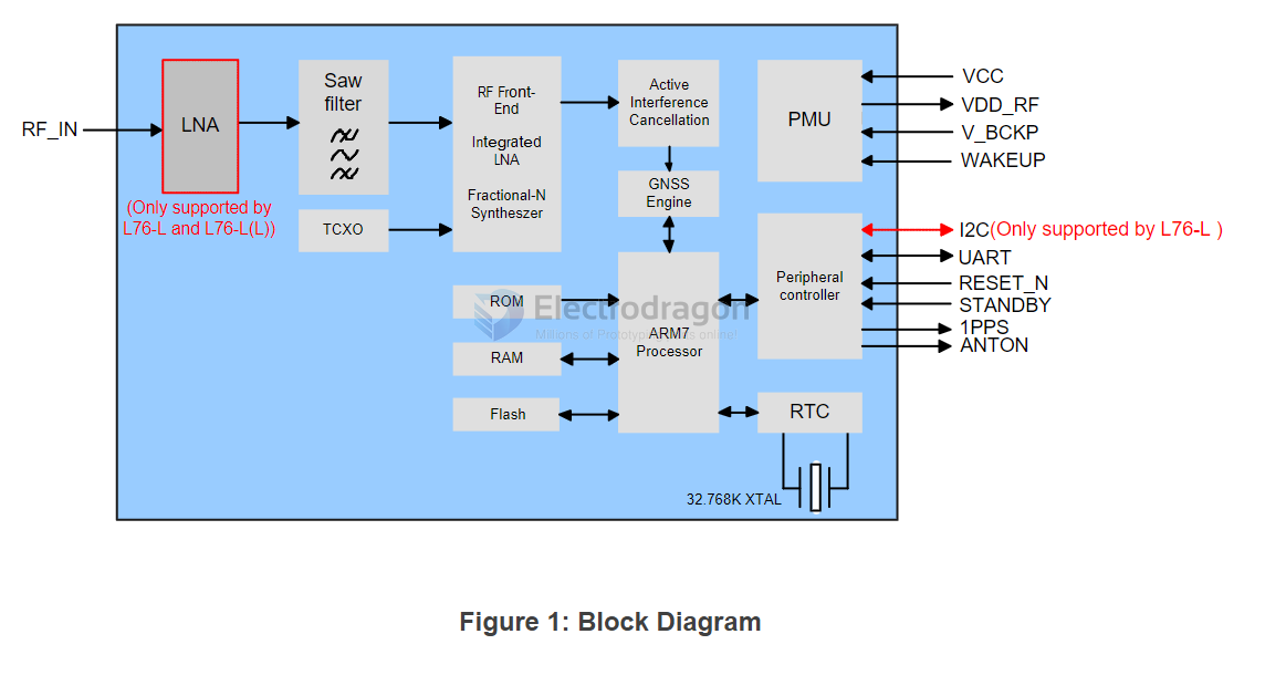
block diagram

standby mode
Pulling STANDBY pin low will make the GNSS module enter Standby mode and releasing STANDBY pin which has been pulled high internally will make the modules back to Continuous mode. Note that pulling down STANDBY pin to ground will cause the extra current consumption which makes the typical Standby current reach to about 600 μA @ VCC=3.3 V.
Sending corresponding command will make the modules enter Standby mode. Sending any data via UART will make the modules exit standby mode as UART is still accessible in Standby mode.
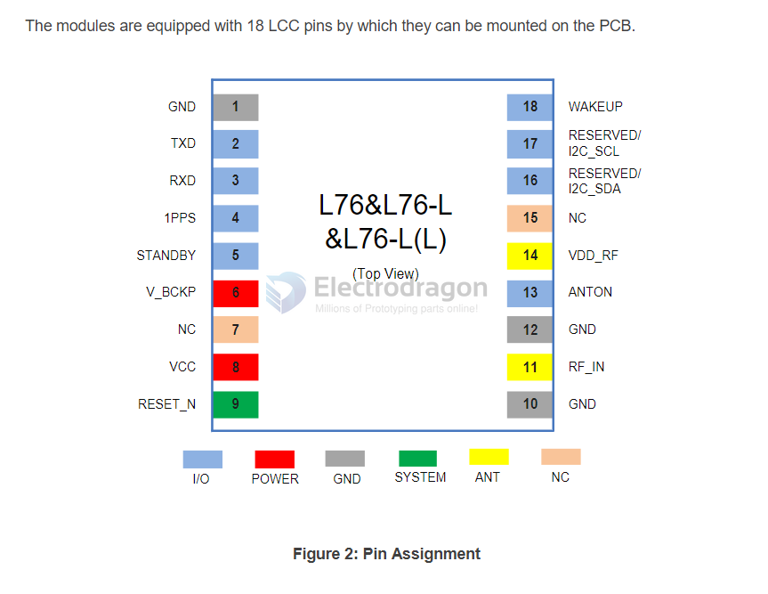
chip map

hardware
antenna design
- There is no need to use an additional LNA for L76-L and L76-L(L) modules, because there isalready an embedded LNA inside these two modules.
- The selected LNA should support both GPS and GLONASS system. For more information, pleasecontact Quectel technical supports.
- The power consumption of the device can be reduced by controlling the LNA ENABLE pin throughthe ANTON pin of the modules. If ANTON function is not used, please connect the LNA ENABLEpin to VCC and keep LNA always on.
version check
- $PQVERNO,R*3f
modules
- L76-K: Quectel_L76K_GNSS_V1.5-1.pdf