Supports SPP Host mode
- Simultaneous Host and Slave operation
- Supports multiple connections
-
SPPcommunication speed: 40 KB/s; -
BLEcommunication speed: 14 KB/s - SPP Host supports connections with up to 7 devices
- Slave mode supports connections with up to 8 Hosts
The EY-34 transparent-transmission module is based on Bluetooth BLE 4.2 and Bluetooth 3.0 standards. It supports BLE and SPP operating simultaneously, and SPP supports multi-connection as well as master/slave operation at the same time—there is no need to separately configure the module as master or slave.
In multi-connect mode SPP supports up to 7 SPP peer connections (Android or PC) plus 1 iOS phone. BLE also supports connections from Android or iOS devices.
In master mode the module can connect to any SPP slave devices on the market (including EY-30, EY-31, EY-32, EY-33, printers, etc.). The communication interface is a standard UART. You can configure working mode, baud rate, BLE UUID, pairing PIN and other parameters via AT commands.
Main advantage: high-speed communication. When connected via SPP to a phone or PC the module supports data transfer up to 40 KB/s and multi-connection functionality.
pins
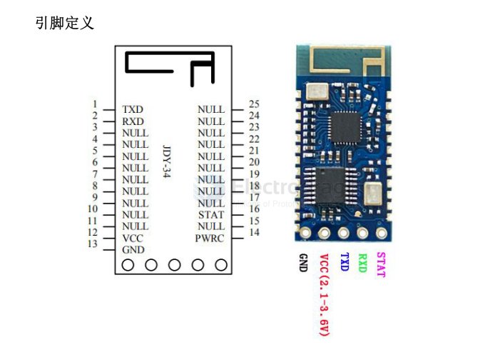
- 12 VCC: power supply (2.1–3.6 V)
- 13 GND: ground
- 14 PWRC: When the module is connected, hold this pin LOW to enter AT-command mode. When the module is not connected, the pin level does not matter — the module will be in AT-command mode regardless.
- 15 NULL
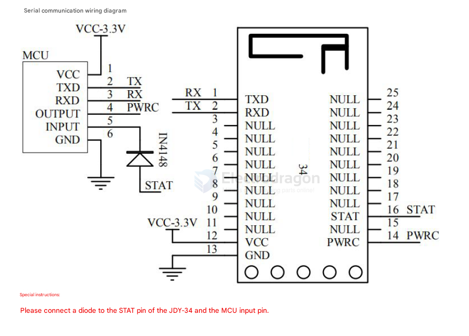
- 16 STAT: low when not connected, high when connected. Connect the STAT signal to the MCU through a diode (or equivalent protection) as required by your design.
SCH
boards
usage
Mode selection
-
For multi-connected printer products, use:
AT+BTMODE0 -
For high-speed transparent transmission with only a phone app or a PC Bluetooth connection, use:
AT+BTMODE1 -
For EY-34 master/slave communication, use:
AT+BTMODE1
Master/slave communication example
Configure both the master and slave as:
AT+BTMODE1
Then follow this sequence:
- The master sends
AT+INQto search for slave devices. - After a slave is found, send
AT+CONAfollowed by the slave MAC address through UART to connect. - After the connection is established, the
STATpin goes HIGH. - The UART also prints connection information, indicating that the link is active.
- Once connected, transparent data transmission can begin.
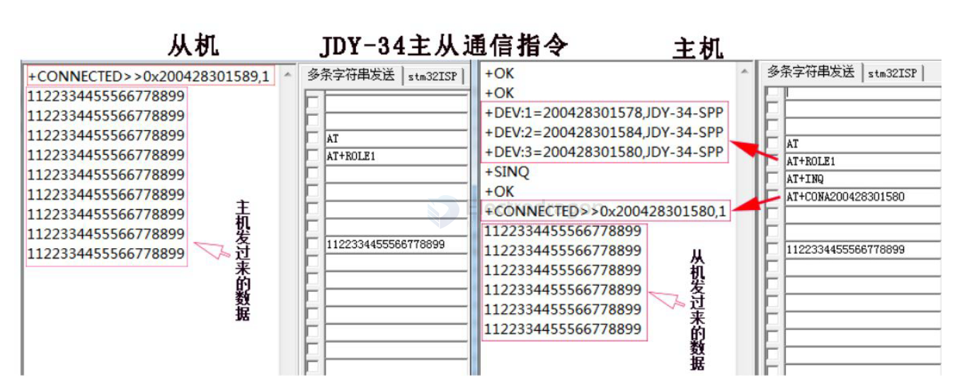
When the slave is connected, it outputs:
+CONNECTED>>0x200428301589,1Meaning:
-
200428301589is the master MAC address. -
1is the current master ID.
When the master sends AT+INQ, the search results may look like this:
+DEV:1=200428301578,JDY-34-SPP
+DEV:2=200428301584,JDY-34-SPP
+DEV:3=200428301580,JDY-34-SPP
+SINQ
This means that 3 slave devices were found, along with their MAC addresses and broadcast names.
If the master chooses to connect to slave 200428301580, send:
AT+CONA200428301580
After the master connects successfully, it outputs:
+CONNECTED>>0x200428301580,1Meaning:
-
200428301580is the slave MAC address. -
1is the slave ID.
Master binding example
In AT+ROLE1 mode, the master can bind to a slave by sending AT+BAND followed by the slave MAC address.
Example:
AT+BAND112233445566
After the master connects to a bound slave, it will keep reconnecting to that same slave as long as the slave remains within range. The master will try to maintain the connection continuously.
To connect the master to a different slave, first clear the current binding with AT+CLRBAND, then bind or connect to the new device.