- [DSE-CN3768.pdf]
Overview
The CN3768 is a complete switching charger controller designed for 12V lead-acid batteries. It provides automatic multi-stage charging with protections and status indication. Typical applications include battery chargers and power backup systems.
Key Features
- Wide input voltage range: 6.6 V to 30 V
- Charge current up to 4 A
- High PWM switching frequency: 315 kHz
- Fixed over-charge voltage and automatic float charging
- Deep-discharge recovery (automatic trickle charge)
- Charge current programmed via a sense resistor
- Automatic recharge when battery voltage drops
- Sleep mode when input voltage is below battery voltage
- Charger status indication (open-drain CHRG output)
- Soft-start and battery overvoltage protection
- Operating ambient temperature: -40°C to +85°C
- Available in 8-pin SOP package
- Pb-free, RoHS compliant, halogen free
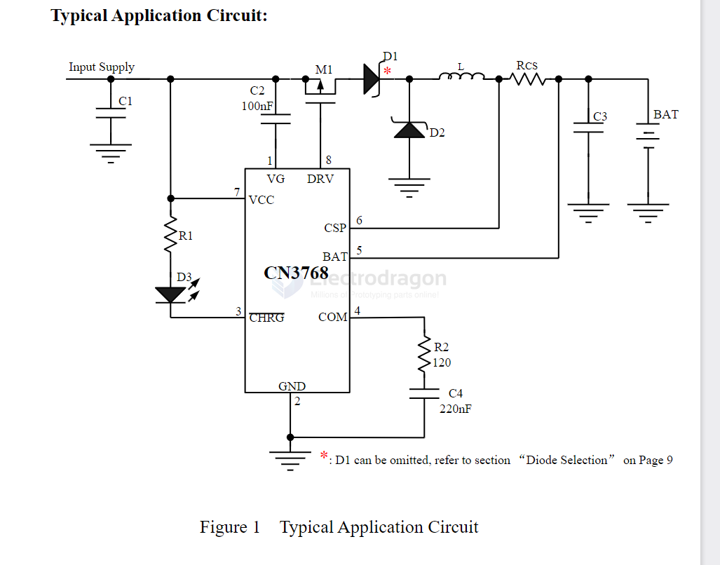
Typical Applications
Electrical Characteristics (summary)
| Parameter | Value | Notes |
|---|---|---|
| Input Voltage Range | 6.6 V — 30 V | Operating VCC range |
| Maximum Charge Current | Up to 4 A | Limited by external components and thermal design |
| PWM Switching Frequency | 315 kHz | Typical internal switching frequency |
| Float (VFLOAT) | 13.35 V / 13.55 V / 13.75 V | Min / Typ / Max for 12 V lead-acid float charge |
| Deep-Discharge Trickle Current | 17.5% of Iprog | Applies until battery reaches 75% of regulation voltage |
| End of Over-Charge → Float | When Ichg ≤ 38% of Iprog | Transition condition to float mode |
| Auto-Recharge Threshold | 83.95% of over-charge voltage | If battery falls below this in float, a new charge cycle starts |
| Sleep Mode | Enters when VIN < BAT | Conserves power when input is lower than battery |
| Operating Temperature | -40°C to +85°C | Ambient temperature range |
| Package | 8-pin SOP | Surface-mount package |
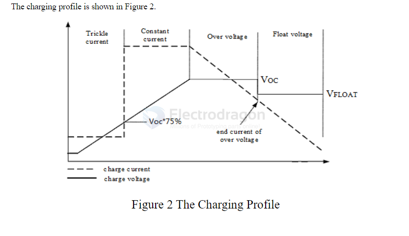
Charging Behavior (summary)
- Deeply discharged batteries: initial trickle charge at ~17.5% of the programmed constant current until battery voltage reaches ~75% of the regulation (over-charge) voltage.
- Constant-current / over-charge: the controller charges at the programmed current until the battery voltage reaches the regulation point; over-charge phase ends when charging current falls to ~38% of the programmed current, then the controller switches to float mode.
- Float mode: a reduced float voltage is maintained. If battery voltage drops below ~83.95% of the over-charge voltage while in float, the CN3768 automatically starts a new charge cycle.
- Sleep: when input (VIN/VCC) falls below the battery voltage, the device automatically enters sleep mode to save power.
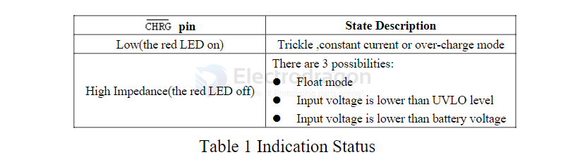
Status Indication (CHRG pin)
The CN3768 provides a single open-drain status output, CHRG. Typically a red LED is connected between VIN (or a suitable supply) and CHRG (with a current-limiting resistor).
| CHRG Output | LED State (red) | Charger Status |
|---|---|---|
| Low (pulled to GND) | ON | Trickle charge, Constant-current charge, Over-charge |
| High-impedance | OFF | Float mode OR VIN below UVLO OR VIN < BAT (no battery present) |
Notes:
- If status indication is not required, tie CHRG to ground.
- When no battery is connected, the charger will charge the output capacitor to the float voltage and CHRG remains high-impedance.
Design Notes
- Program charging current using the recommended sense resistor per the datasheet (Iprog determined by sense voltage / Rsense).
- Ensure thermal layout and component selection (inductor, diode, MOSFET) match the target current and power dissipation.
- Follow the datasheet for recommended input/output capacitors and compensation parts to ensure stable operation.
References
- [DSE-CN3768.pdf] — CN3768 datasheet / application notes