This tutorial will help you quickly understand and use the STH1023 UV/light sensor module. It covers register settings, serial communication, and example commands in clear English.
1. Register Map
| Address | Name | Description | Default |
|---|---|---|---|
| 0x00 | Device ID | 1~254; 0=broadcast; default 0xA4 (must be even, matches 8-bit I2C address) | 0xA4 |
| 0x01 | Baud Rate | 0~8: 2400, 4800, 9600, 19200, 38400, 57600, 115200, 230400; default 9600 | 9600 |
| 0x02 | Update Rate | 0:1Hz; 1:5Hz; 2:10Hz; default 10Hz | 10Hz |
| 0x03 | Output Mode | 0: Continuous (default); 1: Query | 0 |
| 0x04 | Output Format | 0: Hex (default); 1: Character | 0 |
| 0x05 | Save Settings | 0x55: Save config; 0xAA: Factory reset | |
| 0x06 | Analog Range | 0: 0~49999lux; 1: 50000~99999lux; 2: 100000~159999lux; 3: 0~159999lux (default) | 3 |
| 0x07 | ALS_Wfac | 0~256: 0~2.56; brightness glass factor (value × 100) | |
| 0x08 | UVI_Wfac | 0~256: 0~2.56; UV glass factor (value × 100) | |
| 0x09 | UVI_H_data | UVI = (UVI_H_data << 8 | UVI_L_data) / 100 |
| 0x0A | UVI_L_data | See above | |
| 0x0B | ALS_H_data | Lux = (ALS_H_data << 16 | ALS_M_data << 8 |
| 0x0C | ALS_M_data | See above | |
| 0x0D | ALS_L_data | See above | |
| 0x0E | Firmware Info | 0~255 |
2. Serial Communication
Frame Structure
| Address | Function | Data | Checksum |
|---|---|---|---|
| 1 byte | 1 byte | N | Low 8 bits of sum |
Supported Functions
| Function | Code |
|---|---|
| Write Register | 0x06 |
| Read Register | 0x03 |
Response Time
| Baud Rate | Response |
|---|---|
| 9600 | ~10ms |
| 115200 | ~1ms |
3. Example Commands
Set Baud Rate to 115200
Send:
A4 06 01 06 B1Response:
A4 06 01 06 B1Set Update Rate to 10Hz
Send:
A4 06 02 02 AEResponse:
A4 06 02 02 AERead Registers
Send:
A4 03 09 05 B5Response Example:
A4 03 09 05 0001008B08 494. Output Modes
Continuous Output
- Set output mode register (0x03) to 0.
- Send read data frame (set start register and count).
Query Output
- Set output mode register (0x03) to 1.
- Send read data frame each time you want data.
Note: Output format is set by the read data frame. Mode is set by register 0x03.
5. PC Software Usage
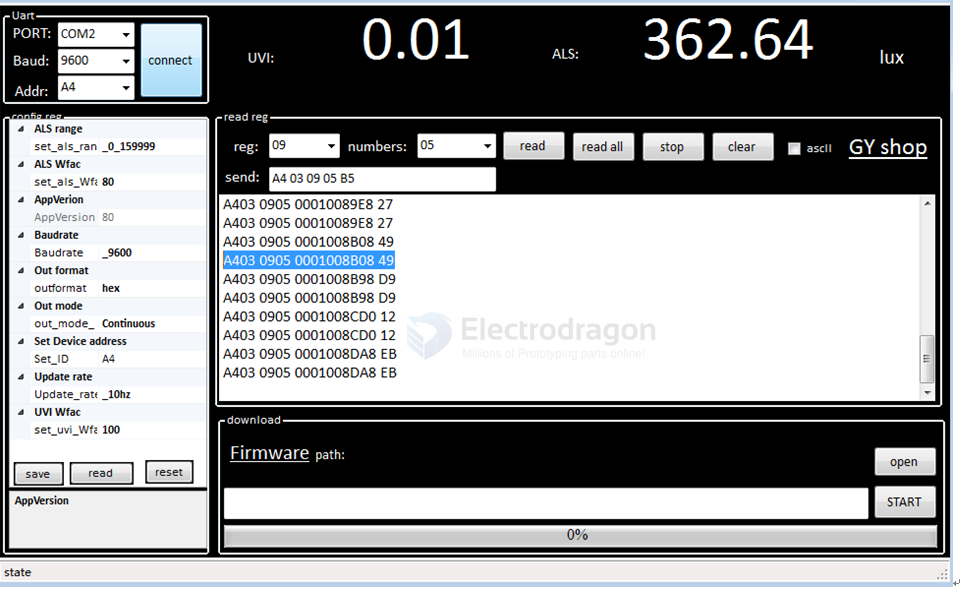
- Use Board-dat/STH/STH1023-dat/GY_UVI.zip for Windows.
- Select the COM port connected to the module, baud rate, and ID (default 0xA4, or 0x00 if unknown).
- Config reg: This section corresponds to configurable registers. After changing any register, press Enter or click elsewhere to write the config to the module.
- Read reg: This section is for reading module registers. Set the start register and number of registers to read, then click "read" to send the command.
Continuous Mode
- Set start register and number of registers to read.
- Set update rate.
- Set mode to continuous.
Query Mode
- Set start register and number of registers to read.
- Set update rate.
- Set mode to query.
- For each query, repeat step 1 (send read register frame).
6. Arduino Example
- See Board-dat/STH/STH1023-dat/arduino_usart.ino for sample code.
Related
- VEML6070-dat
- sensor-UV-light-dat d:每次查询,进行一次a步骤,即每次发送读寄存器指令帧;