https://www.electrodragon.com/product/esp-01-breakout-board/
V2 Version
- Add onboard LDO regualtor AMS1117, input voltage can be 5V, provided stable power supply
- Add pull up and pull down control resistors for booting, pin 0, 2, EN, RST
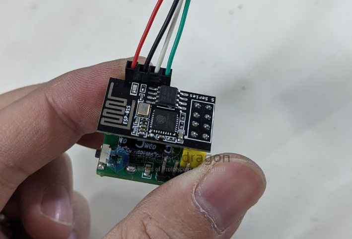
- tested working well for both ESP-01 or ESP-01S
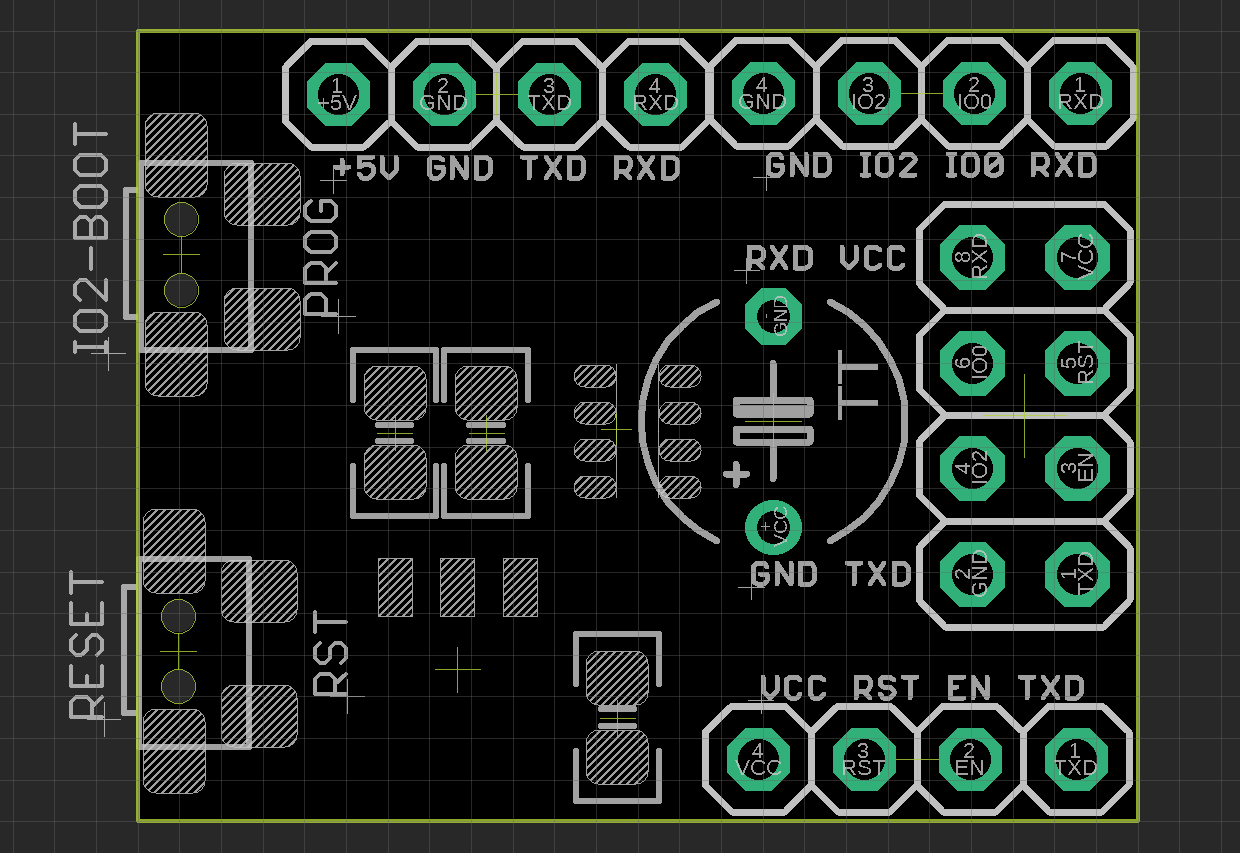
- Two booting control buttons, hold down IO button and press RST button to enter into flash mode.
- Lead all pins 2*4 out to breadboard
Use Guide - Flash
- Hold down PROG button and press Reset button
V1 version
Note:
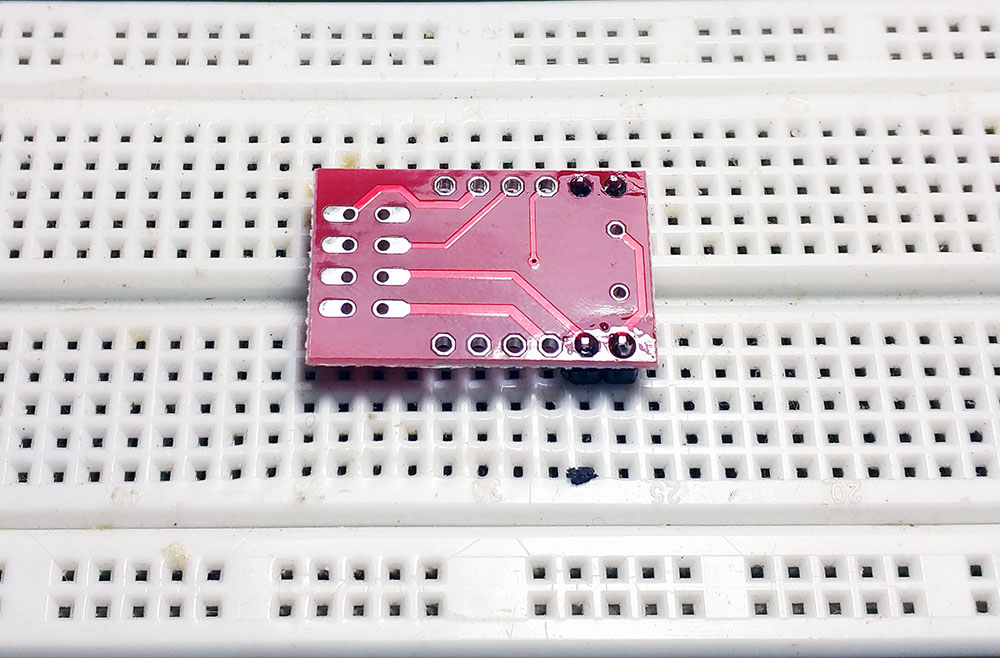
- This board is a kit, NOT soldered, you must soldered by yourself.
- NOT include ESP-01 Board
Features:
- Lead all pins 2*4 out to breadboard
- One group of pin to connect VCC with CHPD to enable the module, by jumper
- One group of pin to connect RST with GND when you want to reset the module, by jumper
- On board current capacitor 220UF
- Only need a USB-TTL tool like CH340 breakout board to connect ESP-01: TX, RX, VCC, GND
Please follow the soldering steps below to solder, otherwise the small board maybe a little difficult to do: