- D2/D3 or D4/D5 Serial to SIM808
- D6/D7 - Relay
- D8 - SIM800 BOOT
- D13 - PROG LED
arduino pin template
| arduino | Note | customize |
|---|---|---|
| 13 | prog_LED | |
| 12 | ||
| 11 | ||
| 10 | ||
| 9 | ||
| 8 | SIM800 BOOT | |
| 7 | Relay2 | |
| 6 | Relay1 | |
| 5 | SIM800-soft_serial | |
| 4 | SIM800-soft_serial | |
| 3 | ||
| 2 | INT0 | |
| 1 | TXD | |
| 0 | RXD |
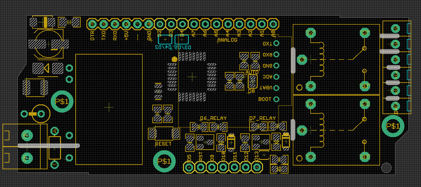
- FTDI FT232RL cable match programming pins on top-left:
- DTR TXD RXD +5V – GND
Accompany Module
hardware Setup
- arduino pro mini 5V/16M
- SIM800 software serial port, selected by SMD jumper: D2 + D3 or D4 + D5
- pull D8 pin to HIGH for at lease 2 seconds, and then LOW to boot SIM800 module
- SIM800 Network LED should start to link
Demo video
- https://www.youtube.com/watch?v=U4_cRzhXZws
Demo Code
- https://github.com/Edragon/Arduino-main/tree/master/Sketchbook/RF/NGS1072
- https://github.com/Edragon/Arduino/tree/master/Sketchbook/01_GSM/
- Please use as a refernece, the repository may need sort out.
Programming
- You will need CP2102 or FT232RL, etc, connect 5V, GND, TX, RX, RST to board relevant pin 5V, GND, RX, TX and DTR.
- A standard FTDI connector wiring image could see here.
- Board pre flashed with arduino pro mini 5V/16M firmware, please choose this as board, and free to upload new code.
Note
- Notice: current board can not fit into our relay board case, AC-DC unit is too big, will make next version supported.
ref
-
SIMCOM-dat/SIMCOM-datSIMCOM-dat]] - ACDC-dat