info
- DMA version
- https://w.electrodragon.com/w/ESP32_DMA_RMP
- https://www.electrodragon.com/product/rgb-matrix-panel-drive-interface-board-for-esp32-dma/
Versions:
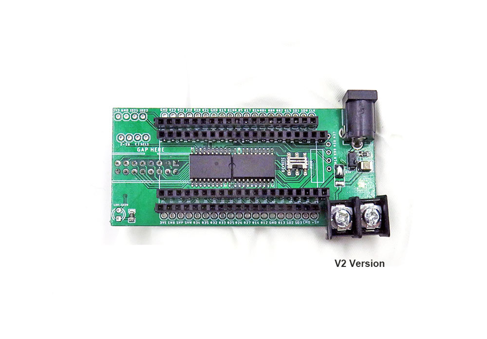
Current V2
- Add logic shifter to shift from signals from 3.3V to 5V
- Lead out alone I2C pin header 4pin
- Lead out alone light sensor IO34
Old V1 version:
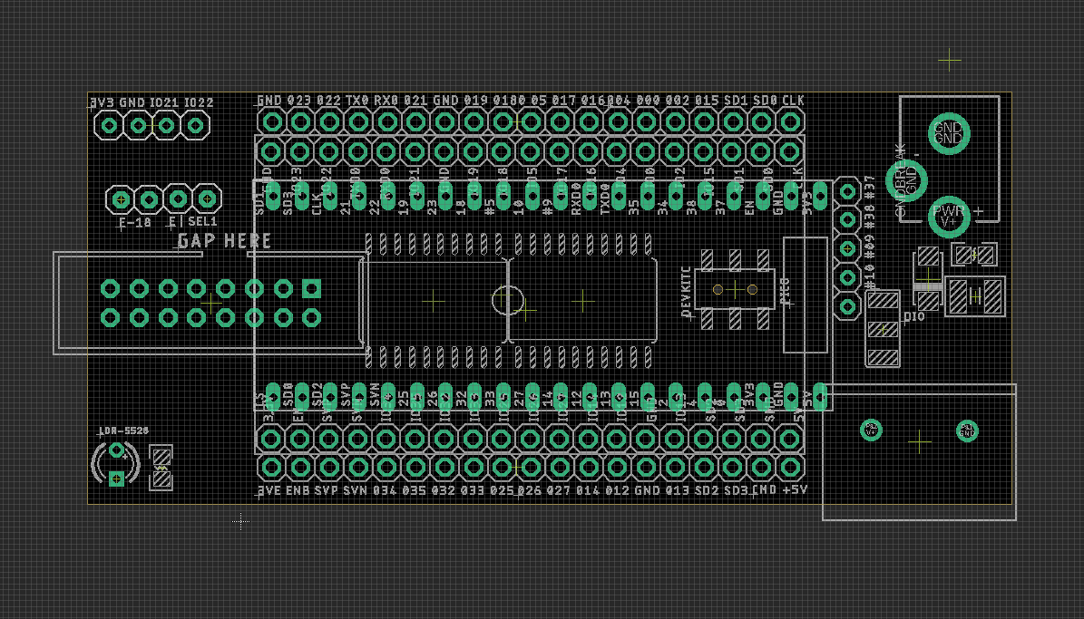
- Lead out all pins for devkitc, but only used pins for driving matrix panel for PICO.
Demos
- V2 version
- https://twitter.com/electro_phoenix/status/1635248053392375808
hardware setup
- swtich between DEVKitC or PiCO
- Please notice for devkitc, CLK = IO16, D = IO17
- Please notice for PCIO, CLK = 32, D = 33
Library Setup
- lib: https://github.com/mrfaptastic/ESP32-HUB75-MatrixPanel-I2S-DMA
- tested sketch: https://github.com/Edragon/Arduino-ESP32/tree/master/Sketchbook/Matrix-panel/IDD1013
Please notice the library updated default setup file
- new setup file: esp32-default-pins.cpp
- old setup file: #include
DEVKITC Board pin definitions
notice the differences of pin CLK and D
#define R1_PIN_DEFAULT  25
#define G1_PIN_DEFAULT  26
#define B1_PIN_DEFAULT  27
#define R2_PIN_DEFAULT  14
#define G2_PIN_DEFAULT  12
#define B2_PIN_DEFAULT  13

#define A_PIN_DEFAULT   23
#define B_PIN_DEFAULT   19
#define C_PIN_DEFAULT   5
#define D_PIN_DEFAULT   17 // pin for devkitc, for PCIO please go IO33
#define E_PIN_DEFAULT   -1 // IMPORTANT: Change to a valid pin if using a 64x64px panel.

#define LAT_PIN_DEFAULT 4
#define OE_PIN_DEFAULT  15
#define CLK_PIN_DEFAULT 16 // pin for devkitc, for PCIO please go IO32
PICO Board pin definitions
#define R1_PIN_DEFAULT  25
#define G1_PIN_DEFAULT  26
#define B1_PIN_DEFAULT  27
#define R2_PIN_DEFAULT  14
#define G2_PIN_DEFAULT  12
#define B2_PIN_DEFAULT  13

#define A_PIN_DEFAULT   23
#define B_PIN_DEFAULT   19
#define C_PIN_DEFAULT   5
#define D_PIN_DEFAULT   33 // different pin for pico
#define E_PIN_DEFAULT   18 // IMPORTANT: Change to a valid pin if using a 64x64px panel.

#define LAT_PIN_DEFAULT 4
#define OE_PIN_DEFAULT  15
#define CLK_PIN_DEFAULT 32 // different pin for pico
setup for matrix size
/*--------------------- MATRIX LILBRARY CONFIG -------------------------*/
#define PANEL_RES_X 64      // Number of pixels wide of each INDIVIDUAL panel module.
#define PANEL_RES_Y 32     // Number of pixels tall of each INDIVIDUAL panel module.
#define PANEL_CHAIN 1      // Total number of panels chained one to another
ENV
- arduino-IDE-DAT - 1.8.19
- lib - version 3.0.5
- esp32 2.0.6
note
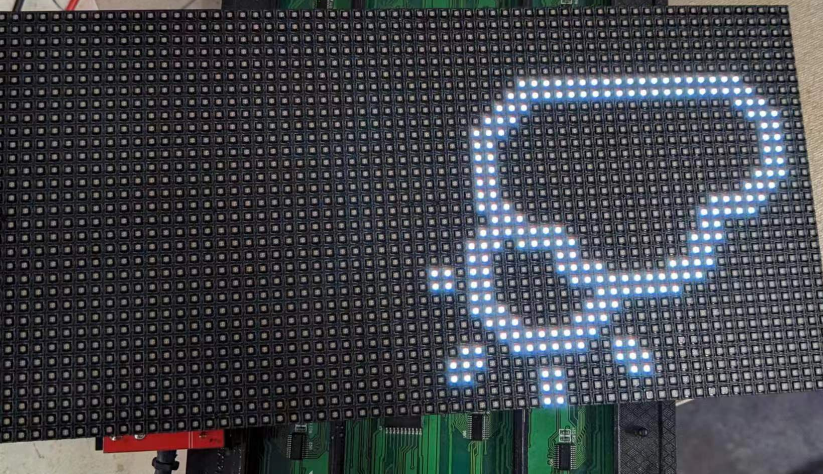
- Tedted with a 32 x 64 panel or 32 x 32
- 64 x 64 will need to setup E-line
- result
Jumper Setup for E-line
- solder pins on E-18 and add jumper
solder pins on E-SEL1 and add jumper
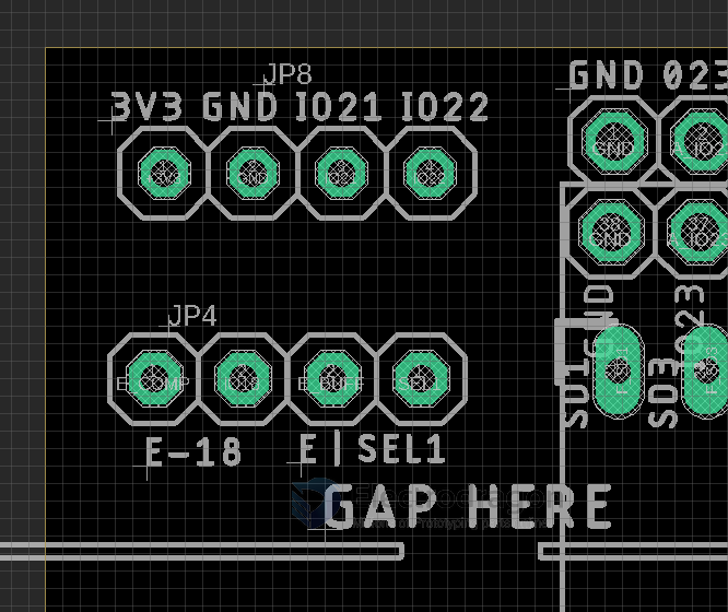
Updated by customer:
- 1) putting a jumper to E-18;
- 2) consider the panel as 64x64 and set number of panels to 2 instead of 1.
Demo video
- https://t.me/electrodragon3/57
- https://t.me/electrodragon3/231