hardware

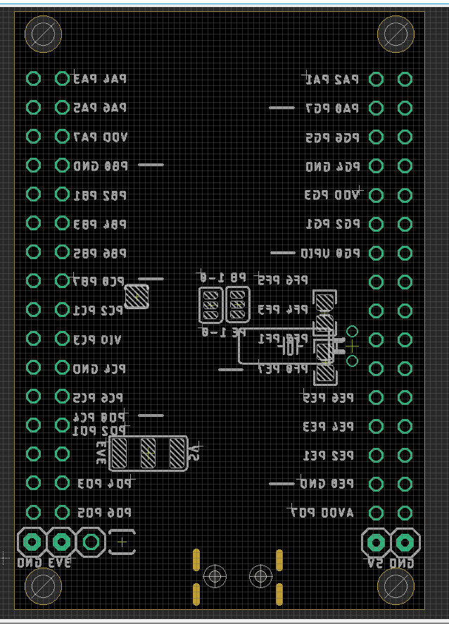
| On board resources | Pin | arduino setup |
|---|---|---|
| prog led | PC6 | D22 |
| prog button | PC7 | D23 |
| Reset | PF6 | reset |
Jumper Setup
| Options | Selections | Default |
|---|---|---|
| Power Supply | 5V or 3V3 | 5V |
| Power Supply of Vdd_io2 | to Vdd | to Vdd |
| USART of Programming | PB0 PB1 (USART 3) or PE0 PE1 (USART 4) | PB0 PB1 (USART 3) |
Usage
- Install Driver for CH340-DAT, check CH340K
- Power LED indicator should be light up
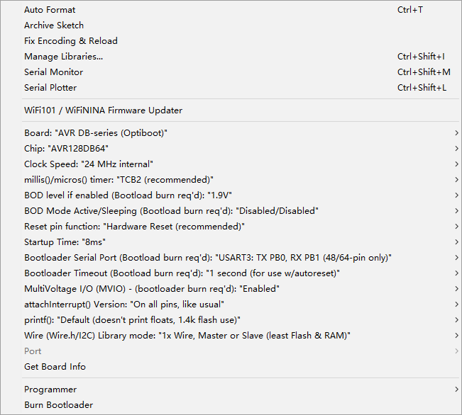
bootloader settings
- Clock -24 mhz internal
- Bootloader serial port: PB0 / PB1
- Reset pin: default
Crystal Setup
- please notice all crystal are not populated, normally use the internal clock is enough
- PF0 / PF1 low speed RTC clock, PTH footprint
- PA0 / PA1 high speed clock , SMD footprint
- crystal-dat
Debug
- Please check if backside jumpers are all soldered or not, power LED is NO or not.
- The full schematic is for purchased customers only, you can also view it directly here.
- Default firmware should be hold down PC7 button and PC6 LED light up, or simple blink sketch. You can find all sketches in our arduino-IDE-DAT
- More information please find at page here.
ref
-
https://w.electrodragon.com/w/Category:AVR128#AVR128_Board
-
UPDI-DAT - CH340-DAT - CH341-DAT - avr128-dat